Hy everybody.

I want to make a programm who accomplish the next tasks : generate a
delay of 3 seconds.
The RD7 pin must stay ON 3 seconds, then must stay OFF 3 seonds, and so
on.

freq. out = freq. clk / (Prescaler*(256 - TMR0)*count)
In my program I work with internal clk (T0CS=0) so the freq. clk is
4Mhz/4 = 1Mhz. ( Period = 1 / freq; internal instruction cycle is 1
microsec).

freq. out = 1 / T = 1 / 3 sec = 0.33Hz and replacing 0.33Hz = 1MHz /
(256 * (256 - 0) * count)
count = 1MHz / 65536 * 0.33Hz
count = 46.

#include<pic.h>
unsigned char counter;
void interrupt Timer0_ISR(void)
{
     if ( T0IE && T0IF )                      // are TMR0 interrupts
enabled and//is the TMR0 interrupt flag set?
        {
             T0IF = 0;                        // TMR0 interrupt flag
must be cleared in software
             ++counter;                       // increment the counter
variable by 1
             if(counter == 46)
             PORTDbits.RD7 ^= 1;              // toggle the RD7 pin
        }
}
Init(void)
{
      TMR0 = 0;                               // clear the TMR0 register
      OPTION_REG = 0B00000111;                // Use the internal
instruction clock, choosing to work with a Prescaler (1 : 256)
      INTCONbits.T0IE = 1;                    // enable TMR0 overflow
      INTCONbits.GIE = 1;                     // enable Global
interrupts
}
main(void)
{
      TRISD = 0B01111111;
      PORTDbits.RD7 = 0;
      Init();
      while(1)
      {
      }
}

I simulate this program with MPLAB SIM but timer0 dont want to
increment.
Please help me.
I dont know if my computations is good.
All the best.
I haven't tried your code, but a few things:

-Add this also to see if it helps  INTCONbits.PEIE = 1
It won't help with TMR0 not incrementing, but I believe it's required
for a timer to generate an interrupt.

-As you are simulating, check the registers you are manipulating to make
sure they really are getting set to what you expect

Otherwise I don't see anything wrong.
Attached files:
-

Untitled_1.jpg
53 KB -

Untitled.jpg
190 KB
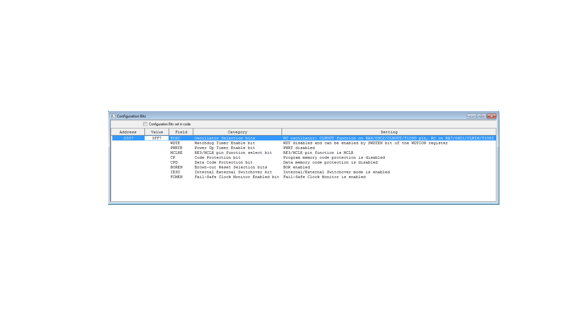

First of all in my opinion i dont think is necessary to set the PEIE bit
(see my attachment), but i tried like you said and not works.
I dont get any compilation errors, the registers are OK.
Is possible to get any error in my "Configuration bits" ?
The only reason I suggest checking the registers in simulation is in
case what you think you are doing ends up doing something else.  Or,
it's possible, not not very likely, that the register name you're using
is incorrectly mapped by the compiler.  Or, something else (I don't know
what) could be changing the bits you set.

I don't see anything in the config bits that would seem to affect TMR0.
I suggest you use PIC18F24J50 insread. It is cheap and it has inbuilt
moduled that enable you to do this. I even managed to program the chip
to communicate via USB and I'm able to directly control its registers
prior to programing it. I first test the programming on a PC and only
when it works I transfer it into PIC. It is easy since you can use C
language on both.
Please log in before posting. Registration is free and takes only a minute.
Existing account
Do you have a Google/GoogleMail account? No registration required!
Log in with Google account
Log in with Google account
No account? Register here.