Hi,

I have "rescued" wonderful 2x20 dot matrix character VF display from
being thrown away.

It was made 10.07.1995 according to the stamp.
It includes  not only the display itsself but a pcb with controller and
different logic chips on it.

Description:
Printing on the PCB:
DISPLAY SYSTEMS M202-MD-07G-2    (the number looks like those used by
FUTABA???)

There is quarz oscillator with 11.0592 (MHz/KHz???)

There are for jumper connectors, with printing:
TEST,RxD1,RxD2,RXD3,RxD4. The last one is jumpered, all others are open.

There are two (!) connectores with 16 pins each. Two pins at one of the
jumpers
are marked GND and VCC.

There is a little coil or trafo -- may be for generating the higher
voltage for the
VFD -- soldered on the PCB.

The VFD itsself consists of 2 rows of characters (5x7 dots each). The
lower row has
also a triangle under each character, pointing down.

On the back of the PCB there a seven chips marked SN75512B made by Texas
Instruments.
There is also one chip marked SG3524 (Texas Instruments) and one chip
marked
MHS
DS SPEEDY1
F1-80C51AXR
(C) INTEL 80, 82
9505 .W31214K

It has eleven pins at each of its sides (44 pins in sum).
This one seems to be the "processor" or "controller"...

I have googled a lot but only foudn either data sheets of bare VFDs
without controller
or descriptions of VFDs with controller, which seems totally different
to mine.

I would be very lucky if it would be poosible to revive this beauty ! :)

Are t!
mcc here any informations about this display, datasheets, links or
whatever
which could help me to reactivate the display?

Thank you very much in advance for any help!

Best regards and have a nice weekend
mcc
Attached files:
-

M202MD07g2-back.jpg
460 KB -

M202MD07g2-front.jpg
650 KB

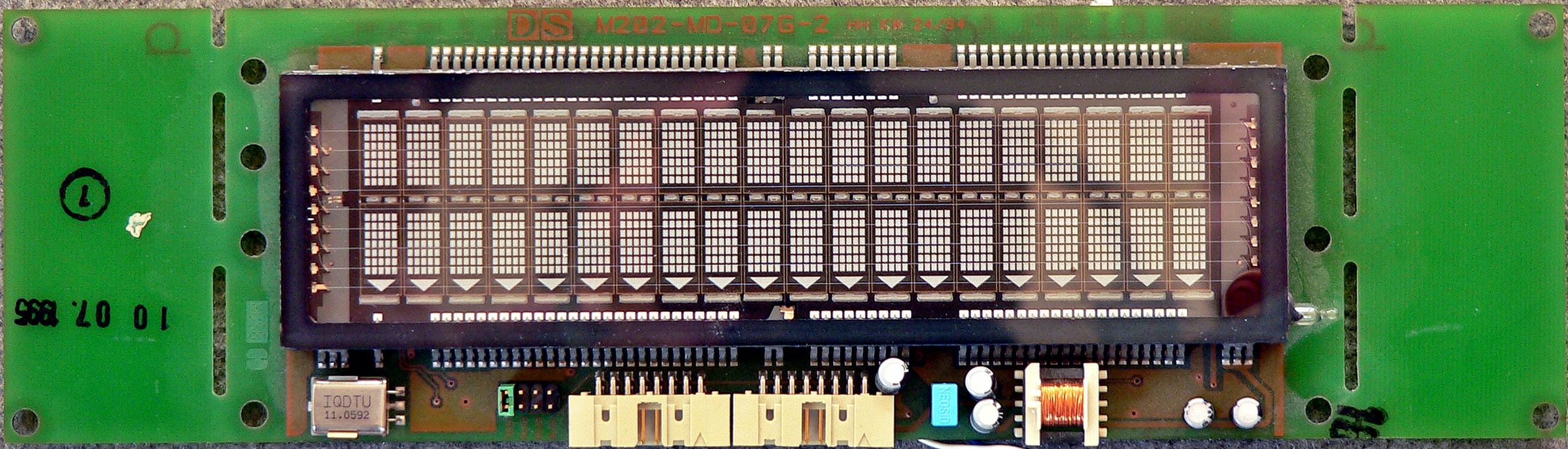
Here are the photos of the VFD...

Best regards
mcc
Well, you know where the power has to go already, I suppose it uses 5
volts.
The "80C51" datasheet will tell you which pins of the controller
represent the serial port RxD and TxD lines, following the PCB tracks
from there, look if it uses a level converter like the MAX232 or
similar. You could try to connect a PC using RS232 (but watch out if
there is no level converter, then you need TTL levels) and try different
baud rates in a terminal program.
Please log in before posting. Registration is free and takes only a minute.
Existing account
Do you have a Google/GoogleMail account? No registration required!
Log in with Google account
Log in with Google account
No account? Register here.