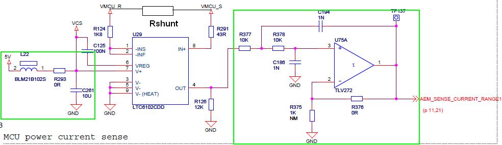
Hi guys,
I posted in the last thread my problem, concerning the measurement of uP
current.
Energy micro has an open source circuit which measures the current
flowing through a sense resistor connected at the supply line of the uP.
please forgive my limited analog design knowledge, and explain to me
what are the two (green highlighted) circuit parts good for?
I thought it is sufficient when the output of the sense amplifier goes
directly to the ADC.

Thx!
Attached files:
-

circuit.JPG
40 KB
Please translate this:
Ich kann nicht in englischer Sprache schreiben, bitte übersetze das
mit einem Translator-Programm:

Auf der linken Seite sitzt ein LC-Filter, um die Betriebsspannung
für den Shunt-Schaltkreis zu "reinigen"

Auf der rechten Seite ist ein Tiefpass-Filter 2.Ordnung zu sehen, um
Störsignale mit hoher Frequenz auszublenden.

Greetings
Paul
left hand side: 2nd order passive LC low pass filter for filtering pesky
noise on the supply lanes. to place close to the diff-amp.

right hand side: also 2nd order but active low pass filter (with
optional gain via R376) for cutting off high-frequency noise gathered
anywhere in the measurment path. cutoff-frequency 100kHz.
in case you want more description on the active low pass filter
it's called sallen key and may also be configured to pass high
frequency components of the signal

http://en.wikipedia.org/wiki/Sallen%E2%80%93Key_topology

you could also use LTspice to analyse the green circuits in the
frequency domain
Hi guys,
Thank you very much for your detailed answers!
When I was looking at the circuit I was not even able to imagine what
each element is responsible for... But now I think I can understand the
things better!
Appreciate it.
Attached files:
-

test.JPG
41 KB
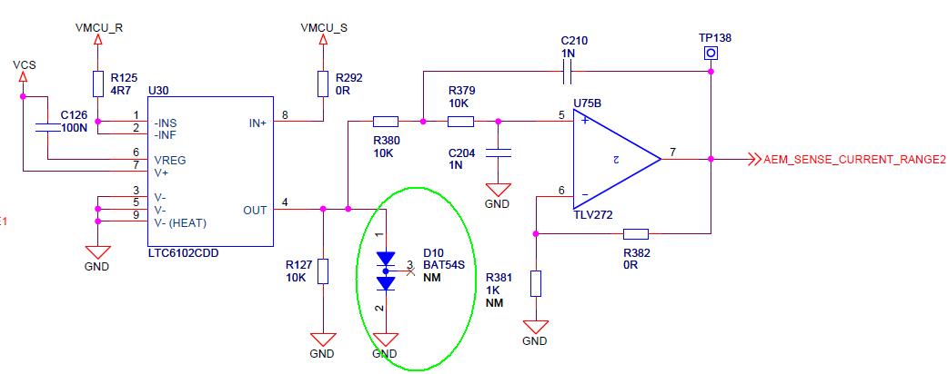
Please guys I have one more question:
for the lower current range, a SMALL SIGNAL SCHOTTKY DIODE was connected
in front of the amplifier. I think it is used to limit the output
voltage of the amplifier to the reference voltage of the ADC, where the
latter signal goes to.
So now how can I figure out, to which value was the voltage limited to?
which parameter is that of the diode? I attached the data sheet for you
review.
Thanks
In the datasheet you will find the formula for the output current of
LTC6102. Calculate the maximum current and imagine that this current is
flowing only through D10. Now have a look into datashett of D10 and find
out what voltage drop corresponds to this current. By this you get the
maximum voltage that is clamped by D10.

In reality only a fraction of this current is actually flowing through
D10, because some current needs to flow through R127 also. So, the
maximum clamped voltage will be slightly lower.
Please log in before posting. Registration is free and takes only a minute.
Existing account
Do you have a Google/GoogleMail account? No registration required!
Log in with Google account
Log in with Google account
No account? Register here.