hi
i want to use pass transistor to design 4 to 1 switch and use vhdl
hat somebody help me?
thanks
> pass transistor
Can you specify what is meant by this term?
A bidirectional 4:1 multipexer?
when you say "i want to use pass transistor" this means, you already
have such a device in your library, right?
Then simply instantiate the component 4 times...
Lothar Miller schrieb:

> A bidirectional 4:1 multipexer?

yes.the task is to design inputswitch use pass transistor instead of use
multipexer.
So you have a component "pass transistor"?
Or do you have to describe such a "pass transistor"?
something like this?
1 | case g0|g1|g2|g3 is |
2 | when "1000" => q <= d0; |
3 | when "0100" => q <= d1; |
4 | when "0010" => q <= d2; |
5 | when "0001" => q <= d3; |
6 | when "0000" => q <= 'Z'; |
7 | when others => null; -- FAILURE, q unpredictable! |
8 | end case; |
Attached files:
-

scan0001.JPG
120 KB
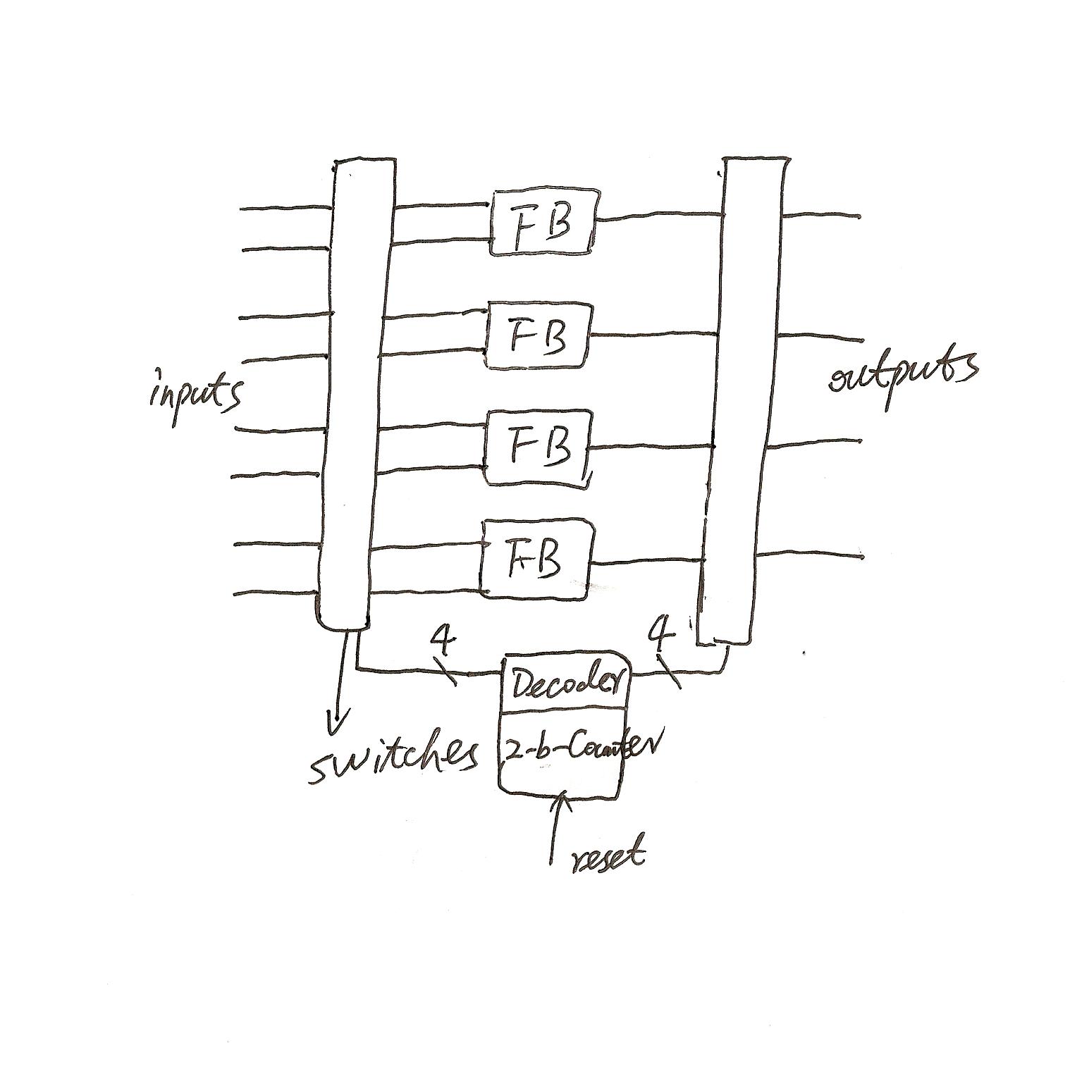
all fb can be 2and or 2nand .use switch to choice a inputsigal to fb and
output too in same fb.
> something like this?
The bidirectional behaviour is missing in this description  :-/

> i have no component.so i have to do it
So this looks like very low-level design. If you want to describe a
bidirectional switch, most of the work will be the resolution
function.
Given the three ports A, B and C you must handle e.g.
what happens if A = '1' while B = '0' and C = '1' (open)
or
what happens if A = '1' while B = '0' and C = '0' (closed)
1 | A
|
2 | |
3 | |
|
4 | |- |
5 | C ----| |
6 | |- |
7 | |
|
8 | |
9 | B
|
So such a pass transistor may look this way:
1 | library IEEE; |
2 | use IEEE.STD_LOGIC_1164.ALL; |
3 | |
4 | entity PassTransistor is |
5 | Port ( A : inout STD_LOGIC; |
6 | B : inout STD_LOGIC; |
7 | C : in STD_LOGIC); |
8 | end PassTransistor; |
9 | |
10 | architecture Behavioral of PassTransistor is |
11 | begin
|
12 | A <= 'Z' when (C='1') else |
13 | '1' when (B='1' and C='0') else |
14 | '0' when (B='0' and C='0') else |
15 | 'X'; |
16 | |
17 | B <= 'Z' when (C='1') else |
18 | '1' when (A='1' and C='0') else |
19 | '0' when (A='0' and C='0') else |
20 | 'X'; |
21 | end Behavioral; |
In a simplified way by using the resolution function od std_logic you
can write
1 | A <= B when (C='0') else 'Z'; |
2 | B <= A when (C='0') else 'Z'; |
> all fb can be 2and or 2nand .use switch to choice a inputsigal to fb and
> output too in same fb.
I urge you to get known to the terms and phrases used in your business.
In your picture theres absolutely no bidirectional path, so its just a
straight forward mux.
Have a look at the code posted by berndl, thats a mux.

But i don't clearly understand your picture. When you have 4 function
outputs and afterwards a mux to 4 signals, which of the outputs must be
routed to which signal. Can you scetch one or two signal paths in your
picture?
What happens here with the other 6 inputs and 3 outputs?

In your sketch you have 4 dual inputs, 4 function blocks and 4 outputs.
This results in 64 possible routings, how can you handle this with a 2
bit input? The main problem to understand is why you have 4 outputs.
Lothar Miller schrieb:


<What happens here with the other 6 inputs and 3 outputs?

other 6 inputs and 3 outputs do nothing.because only one funktion block
aviable with the switch
> other 6 inputs and 3 outputs do nothing.
"Nothing" is no option. For shure they will do something  ;-)

OK, lets give the kids some names:
1 | inputs functions outputs |
2 | in0a fb0 out0 |
3 | in0b |
4 | |
5 | in1a fb1 out1 |
6 | in1b |
7 | |
8 | in2a fb2 out2 |
9 | in2b |
10 | |
11 | in3a fb3 out3 |
12 | in3b |
Are the only routing possibilities e.g. in0 - fb0 - out0
or in1 - fb1 - out1 ...

Or can e.g. the in0 ever be routed to out3 through fb2?
Looks like homework...

Maybe his teacher should help him or he should attend school
regularly...
Lothar Miller schrieb:
>> other 6 inputs and 3 outputs do nothing.
> "Nothing" is no option. For shure they will do something  ;-)
>
> OK, lets give the kids some names:
>
1 | > inputs functions outputs |
2 | > in0a fb0 out0 |
3 | > in0b |
4 | > |
5 | > in1a fb1 out1 |
6 | > in1b |
7 | > |
8 | > in2a fb2 out2 |
9 | > in2b |
10 | > |
11 | > in3a fb3 out3 |
12 | > in3b |
13 | > |
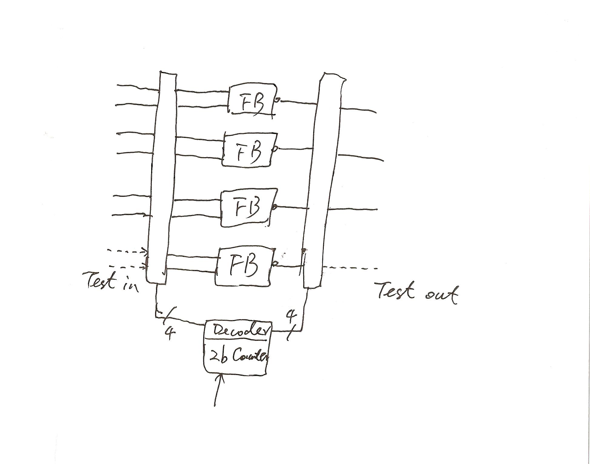
> Are the only routing possibilities e.g. in0 - fb0 - out0
> or in1 - fb1 - out1 ...
inoa in0b  fb0 out0


> Or can e.g. the in0 ever be routed to out3 through fb2?
this can be in3a in3b fb1 out3 too
> this can be in3a in3b fb1 out3 too
So it will be
inXa inXb   fbY  outX     with (X=0..3, Y=0..3)
but never
inXa inXb   fbY  outZ     with (X=0..3, Y=0..3, Z=0..3, Z/=X)


So how do you select one of the 4 input pairs to one of the 4 fb input
pairs (these are 4x4=16 possible ways) with only 2 bits?
Dong Wang,
probably you could just explain, what you really want to do with this
piece of hardware.
* What type of signals are the inputs? Analogue, LVDS, just digital '0'
and '1', serial data? Or what else?
* What is expected as output?
* And what should the 2-bit counter do?
* And, most important, what should this circuit really do?

Otherwise I'll stop reading deep in my coffee-mug...
Nichts gegen Tipps von Hobbyist zu Hobbxist, oder von Fachmann zu
Fachmann, aber schon mal gedacht dass man sich damit schwer schlagbare
Konkurrenz schafft.

Es heisst ja Erfahrungsaus-t-a-u-s-c-h , wobei dieser Anfrager fachlich
nicht viel zum tauschen hat.

MfG

I am not against Exchanging KnowHow between hobbyist or from Expert to
another. But have you ever given ist a thought, thats that makes a hard
to beaten competition.

It's called ex-C-H-A-N-G-E, but this applicant has nothing to swap.

Best regards
> ... dass man sich damit schwer schlagbare Konkurrenz schafft.
Glaube ich nicht, bzw. macht mir keine Sorge   ;-)
Lothar Miller schrieb:
>> other 6 inputs and 3 outputs do nothing.
I think it should work like this:
- One of the "2-inputs" on the left should be switched to the input of
ALL function blocks in the middle (the rest three left inputs are
ignored)
- One of the FB outputs schould then be selected as output (the rest are
High-Z, don't cares or holding the last output)

Probably for a testing devices/input one after the other with just
needing the 4 Input blocks once.

Grashalmlängenkontrollminister schrieb:
> Looks like homework...
I agree with that especially the terminus 'pass transistor' more sounds
like he should construct a complex-cmos-device than a VHDL code...

Because when my assumption is true, this task could be more easily be
acomplished by a pipeline than by such a strange
"pass-transistor-design"...
Search for e.g. "trans", "nmos" or "pullup" in the verilog LRM.
Simulation only!
Driven by the electronization of cars at large, vehicle-used PCBs will
also increase. Vehicle-used PCBs are characterized by having steady
order and high gross profit rates, which have drawn great attention from
many PCB insiders to this new blue ocean. Vehicle-used PCB are mainly
oepratd in a high-speed context, which made the requirements for this
kind of PCB higher than that of ordinary ICT products specifications in
terms of temperature resistance, electromagnetic waves proof, earthquake
proof and corrosion resistance. As a result, to guarantee the quality of
car parts and ensure the life safety of driving and passengers is an
important issue faces by all the car manufacturers; whether car parts
vendors can provide a long-term and stable quality is far more important
than that of the low-price ones. Besides, the car manufacturers’
inspection for products tends to last as long as three years. Therefore,
PCB manufacturers who would like to march into the car electronic syply
chain usually need more patience and strength. http://www.pcbindex.com
Please log in before posting. Registration is free and takes only a minute.
Existing account
Do you have a Google/GoogleMail account? No registration required!
Log in with Google account
Log in with Google account
No account? Register here.