Hi,

I am new to VHDL and I have a stupid question, maybe.
What I have learned up to now is, that I have to write those signals
that a process should react on, into its sensitivity list.
So, for a counter, I have to write at least the clock signal into the
sensitivity list, right?
And the process is activated only if one of the signals in the
sensitivity list changes, right?

So, I would really like to know if there is a difference (and if yes:
what exactly this difference is?) between

process (CLK)
begin
  if CLK='1' then
    CNT <= CNT+1;
  end if;
end process;

and

process (CLK)
begin
  if CLK='1' and CLK'event then
    CNT <= CNT+1;
  end if;
end process;

What is this "CLK'event" for? Do I need it really or is it there just
for improving the readability of the code?
Again: as far as I understand, the process is activated only when the
CLK signal changes (i.e. at a rising or falling edge), so the condition
CLK'event seems to be redundant. Am I right or am I wrong?

Regards,
Christian
The  'event  means any change on the signal.

So this
1
ifCLK='1'then...
does implicitly exactly the same as
1
ifCLK='1'andCLK'eventthen...
because the process is calculated only, when any signal in the
snsitivity list (here only CLK) changes its value.

> Do I need it really
No, not REALLY
> or is it there just for improving the readability of the code?
Its common to write it that way. And the best is, not to go too far away
from the "common".

For best readability try this:
The sensitivity list is only relevant for the simulation. Your first
process does not make sense to the synthesizer, it describes a feedback
loop without a clock that can not be implemented in a sensible way. The
second process is a clocked process and can be implemented.

Remember that, unless you are writing code only for the simulator, you
are not using a programming language, but a synthesis language. You can
not use all the functionality of VHDL at your will, you are restricted
to what your synthesizer understands. There are two basic kinds of
processes you can use if you want to describe a design that is
synthesizeable:

Combinatorial process (no 'event or rising_edge, all signals in the
sensitivity list):
1
process(a,b,c)
2
begin
3
y<=a+b+c;
4
endprocess;
Clocked process ('event or rising_edge, only clock in sensitivity list):
Thanks to Lothar, thanks to Andreas,

I've now tried the three different versions

1.
  if CLK='1' then...
2.
  if CLK='1' and CLK'event then...

and
3.
  if rising_edge(CLK) then...

with Quartus (V7.2) and downloaded them to my FPGA. The FPGA behaves
identical, so I conclude that all 3 version are treated equal by the
synthesizer.
Andreas, is this a 'sleazy' bug in Quartus? Should I get a warning when
synthesizing version #1? I am just curious.

Regards,
Christian
> The FPGA behaves identical, so I conclude that all 3 version are treated> equal by the synthesizer.
This is a strange way to testify the equality of VHDL descriptions :-o
First must be a look on the RTL schematics. There you can check whether
the synthesis results are the same or not.
But in your case I assume the results are the same ;-)
> is this a 'sleazy' bug in Quartus? Should I get a warning when> synthesizing version #1?
I don't think so.
In a simulation of version #1 the process is calculated, when CLK
changes. an inside the process CLK is checked for '1'. So the
synthesizer is capable of translating this description to correct
hardware, that behaves like the simulation.
A few versions ago synthesis tools were not able to cope with this
style:
1
processbegin
2
waituntilrising_edge(clk);
3
:
4
:
5
endprocess
Now they are able to get hardware out of this description. But from the
beginning on this description was able to be simulated.
Thanks for your comment, Lothar,

meanwhile, I've found and checked the RTL schematics and found them to
be equal in all 3 cases.

One question, at last:
Why do you prefer writing the process in your preferred style as

process begin
  wait until rising_edge(CLK);
  CNT <= CNT+1;
end process;

What is the advantage of that?
Sorry for so many newbie-questions!

Christian
> What is the advantage of that?
Becuase you don't have any sensitivity list, you cannot have a
incomplete sensitivity list. So the simulation and the resulting
hardware is always consistent.

Given this #1 style description:
1
process(clk)begin
2
if(clk='1')then
3
outp<=inp;
4
endif;
5
endprocess;
I just want to add a reset signal:
1
process(reset,clk)begin
2
if(reset='1')then
3
outp<='0';
4
elsif(clk='1')then
5
outp<=inp;
6
endif;
7
endprocess;
Due to a extending your #1 style description with a asynchronous reset,
this will no longer be synthesized as a flipflop. It will result as a
transparent latch in the hardware: when clk is '1' then inp will be
directed to outp    :-o

But the simulation will look different, because the process will be
calculated only on a change of one of the signals reset and clk. And the
simulation will check for clk='1' and therefore behave like a fliflop.

So we have in
hardware:   latch
simulation: flipflop

Believe me: that will cost you some hours of debugging...

For a correct simulation of the incorrect description of the flipflop it
would be necessary to complete the sensitivity list this way:
1
process(reset,clk,inp)begin...
Now the simulation and the hardware will show the erroneous latch.


BTW:
This is also a reason not to use your description #1   ;-)
Just to be picky, Lothar,
but the simulation of the above description with the reset gives not a
FF, but a mixture between FF and latch, something simply not available
in hardware.
When reset goes to '0', and inp did change in the meantime the output
jumps to the new value, simply as a latch with reset would do.
On the other side it does not react to inp, somethibg a real latch would
do.

It would be therefore better to say that the modification of the
sensitivity list to
1
process(reset,clk,inp)begin...
corrects the description to behave now correctly like a latch, something
the synthesis had probabely assumed erroneously.

It's a pity, but this discussions could all be avoided if the synthesis
compilers would not accept erroneous sensitivity lists.
> Just to be picky ...
Ok, one more strange behaviour   :-o

Now I synthesized this 4 descriptions with Xilinx XST:
1
entityClockStylesis
2
Port(clk1:inSTD_LOGIC;
3
i1:inSTD_LOGIC;
4
o1:outSTD_LOGIC;
5
clk2:inSTD_LOGIC;
6
i2:inSTD_LOGIC;
7
o2:outSTD_LOGIC;
8
clk3:inSTD_LOGIC;
9
i3:inSTD_LOGIC;
10
o3:outSTD_LOGIC;
11
clk4:inSTD_LOGIC;
12
i4:inSTD_LOGIC;
13
o4:outSTD_LOGIC);
14
endClockStyles;
15
16
architectureBehavioralofClockStylesis
17
begin
18
19
process(clk1)begin
20
if(clk1='1')then
21
o1<=i1;
22
endif;
23
endprocess;
24
25
process(clk2)begin
26
if(clk2='1'andclk2'event)then
27
o2<=i2;
28
endif;
29
endprocess;
30
31
process(clk3)begin
32
ifrising_edge(clk3)then
33
o3<=i3;
34
endif;
35
endprocess;
36
37
processbegin
38
waituntilrising_edge(clk4);
39
o4<=i4;
40
endprocess;
41
42
endBehavioral;
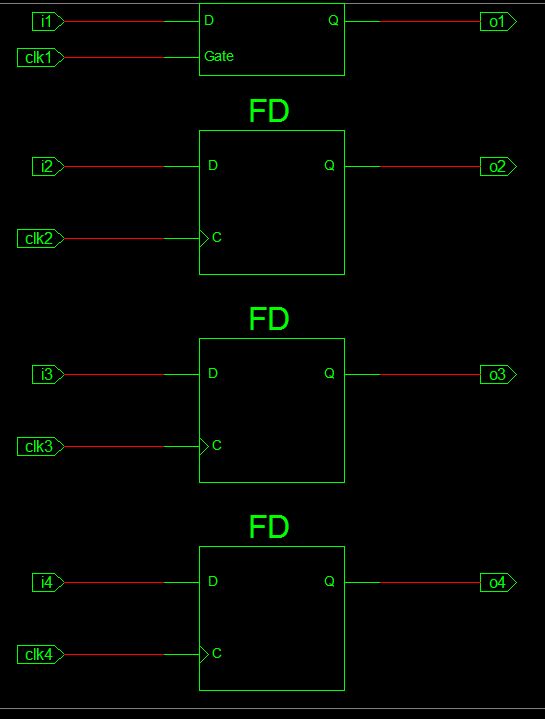
During synthesis I got a warning:
1
WARNING:Xst:819 ... The following signals are missing in the process sensitivity list: i1
As a result I had a look on the RTL schematics (attachement).
The signal i1 was added automatically to the sensitivity list of process
#1 and therefore a latch was generated.
In contrast Christian said:
>> meanwhile, I've checked the RTL schematics and found them>> to be equal in all 3 cases.
So here the Xilinx tools act very different to the Altera tools :-(
i am a be 2nd yr student. so iwant some knowledge abt vhdl coding. pls
explain the logic of vhdl code to control the speed and direction of
simple dc motor?
