Custom ESP8266 Board unable to connect

OP #7831518
Rate this post
useful
not useful

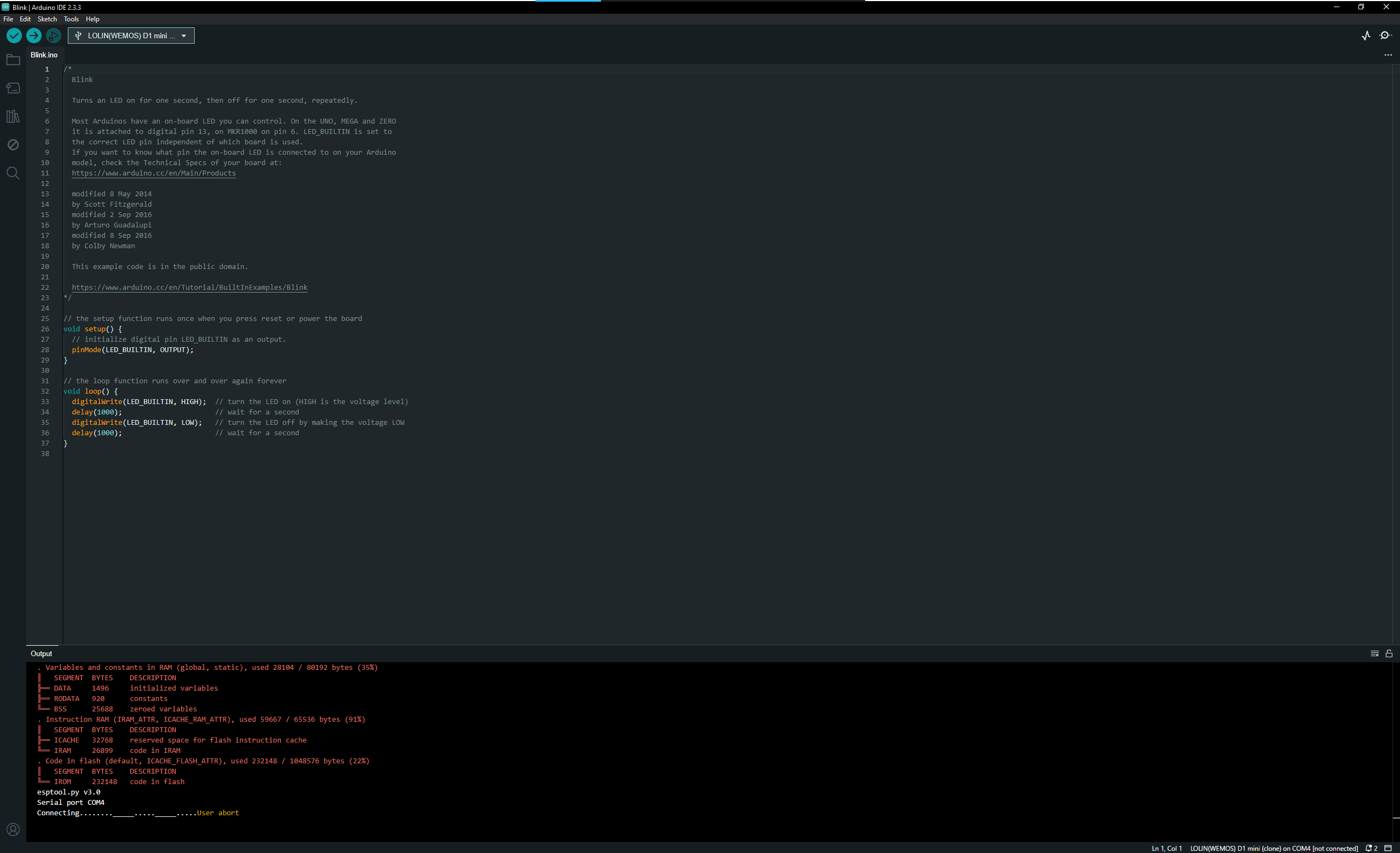
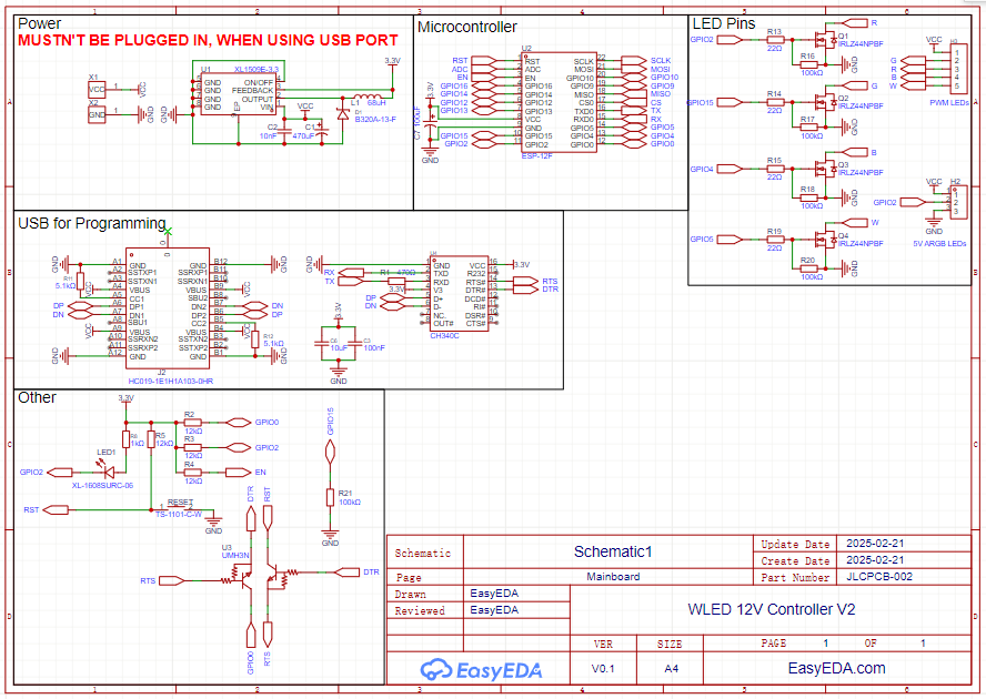
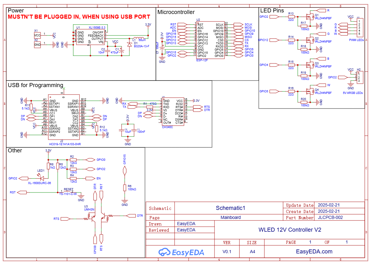
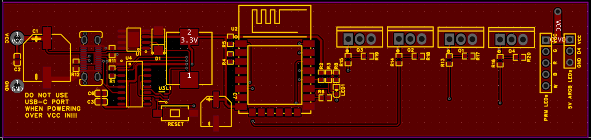
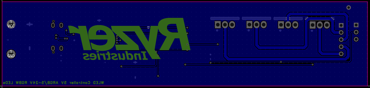
Hello there I have made a custom ESP8266 board with which I want to operate WS2812 LEDs with WLED. I have received and assembled the PCBs and wanted to upload the blink sketch for testing with the Arduino IDE. However, I get an error message in the console that no connection could be established. Do I have an error in my schematic? Any help is gratefully appreciated.

Moderator (Company: Titel) #7831556
Rate this post
useful
not useful

Stephan B. wrote:

Any help is gratefully appreciated.

Usually it first time operation doesn't work the way "switch the power on and all runs ok". Instead you must do it stepwise:

  1. apply supply voltage
  2. measure the supply voltages on the devices supply pins
  3. bridge rx and tx at the CH340 and check it with a terminal programm
  4. ....
  5. ..

Any help is gratefully appreciated.

The pins in good readable schematic symbols are not sorted in the package order. Instead they represent the function of the device: inputs right, outputs left, supply top and bottom. Simply have a look at other good readable schematics. Compared to them yours looks a little bit like the scribbling of an kindergarten child.

J. S. wrote:

the antenna from the ESP is perfectly shielded.

First thing is to read the data sheet and second is to have a close look on other boards.

OP #7831849
Rate this post
useful
not useful

Thank you, for your recommendations. Currently I am not having an error connecting to it wirelessly, I habe trouble uploading a sketch, I get the feedback that it failed to establish a connection. Also, when it tries to connect, the builtin LED blinks for 10ms or so and then goes dark for another 2s.

And yes, I know the design isn't really good, since it is my first ever ESP32 custom PCB _:) I am just trying to get this to work, so I can install WLED to it, then I can improve my design and do a 2. Rev

Guest #7831968
Rate this post
useful
not useful

You need a 100µF capacitor near to VCC/GND pins of the ESP12 module.

GPIO15 needs a pull-down resistor.

U3 must be connected to GPI0, not GPIO10.

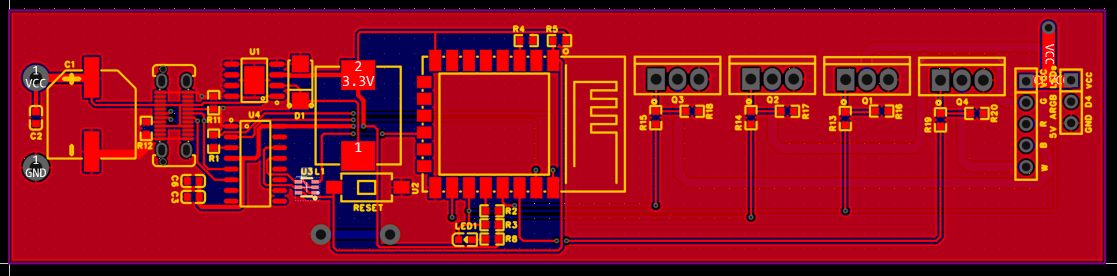
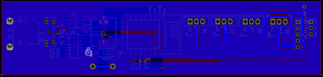
The pin row on the short side (opposite of the antenna) must NOT be connected, because they are used for the flash memory.

See http://stefanfrings.de/esp8266/index.html

Notice the "translate" link in the upper right corner.

#7849154
Rate this post
useful
not useful

If you're having trouble uploading sketches to your ESP8266 board, ensure the USB-to-serial converter (TX-RX swapped) is properly connected, drivers are installed, and GPIO0 is pulled low during reset. Use a stable 500mA power supply, keep the antenna area clear, and compare your design with Wemos D1 Mini. If using the THGBMNG5D1LBAIL eMMC module which you can find https://www.xecor.com/product/thgbmng5d1lbail here, verify correct integration, as improper connections may affect functionality.

OP #7852357
Rate this post
useful
not useful

I have now changed my design and built the new PCBs, but the issue is the same, when I try to connect and flash the blink sketch with Arduino IDE to the ESP, the led just flashes a few times as like it is resetting and then the Console tells me, it is unable to connect to the device. For Programming I am using the LOLIN D1 mini for the board and I have correctly installed the CH340 Drivers, I also tried six different USB cables and the GPIO0 is effectively tied to ground when trying to flash. I attached my design, if anyone wants to thinker with it, have a go, and let me know if you find out anything useful. I am not able to find out what it is... I am redesigning the PCB to use a already built microcontroller board, I am thinking of the XIAO ESP32, since building you own ESP seems to be rather unnecessary complicated. Thank you very much for every help provided to this point.

Attached files:

Reply

Please log in before posting.

or

Log in with Google account

Registration is free and takes only a minute.

Register now