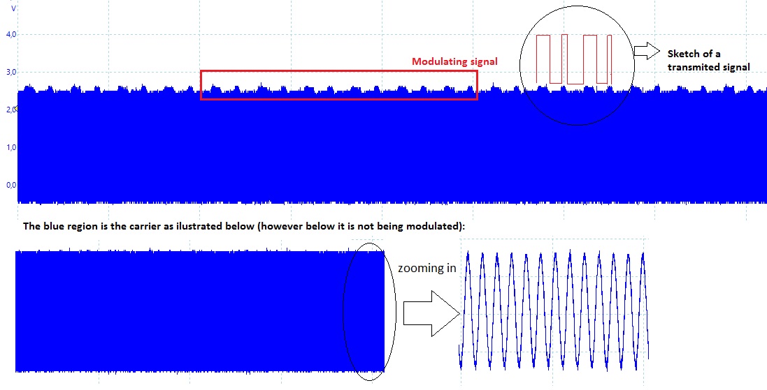
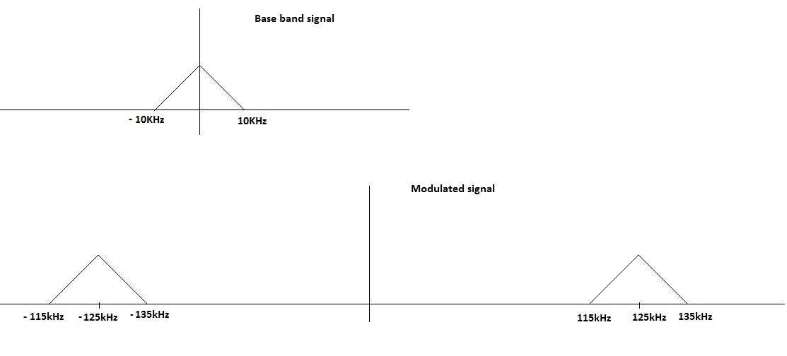
I'm trying to read a LF(Low Frequency) transponder, it works in the
following manner: It uses load modulation, the receiver generate the
carrier and the transponder modulates it using magnetic coupling(like a
electrical transformer). The tag being read switch a load (resistance)
and it changes the carrier's amplitude like can be seen in the figure
modulation_1.

The information being modulated, as can be seen, is very weak compared
to carrier's amplitude. The carrier frequency has 125kHz and the base
band signal has a 20kHz bandwidth.

The figure modulation_2 the signals were sketched in frequency domain.

I have only a dsp to process this signal and a conditioner circuit to
put the signal received in an appropriate voltage level. I assume that
amplitude demodulation would be a better approach to solve the problem.

After the sampled signal go through the filter I perform a amplitude
level comparison to decide in wich logical level to translate in bits( I
determine this level experimentally ). But, this is not being good
enough, the amplitude level after filtering is very low and there is a
DC( constant value) component present after filtering. The level of
amplitude can vary to diferent tags being read and the comparison to
detect the logic level may not be a robust approach.

To design the low pass filter I used a windowed sinc with window
function Kaiser-Bessel. Frequency sample of 900 kHz, -3dB frequency of
30kHz and 12 taps(coeficients).I'm using  dsPIC33EP it's sampling rate
can reach up to 1MHz and the DSP core can reach up to 70 MIPS.

Please, I don't know what to do anymore, so, whatever tip will be very
appreciated.
Attached files:
-

modulation_1.jpg
130 KB -

modulation_2.jpg
31 KB
I am not really an expert but the problem sounds interesting. But I have
some questions about this. And please apologize my simple english.

1) Why do you use such a high samplerate? This would make it harder to
design a good lowpass because the corner frequency is narrower to the
edges of the passband.

2) What is the amplitude range of the signal and how many bits are used?

3) What kind of signal is that? Is that something like a Manchester
code? Is it free of DC bias? In this case you can use a simple moving
average to get a decision threshold.

4) And why you are using only a 12 tap FIR? Is this a hardware
limitation? If so I think you should also try to calculate a 14 tap
filter and use a Von-Han, Lanczos or a Cosine window. These windows will
make the first and the last coefficient to be zero and so I think they
don't need to be realized in hardware.

In the last point I may be completely wrong, just an idea.
:
Edited by User
ok, I'm not an expert either, far from it. I'll apologize for my bad
english, it is not good too. Anyway, thank you in advance for your
attention.

1)  I used a high sample rate, it was at the begining,  because when I
used I thought it would be better, but when I used a lower sample rate,
but still respecting the Nyquist sampling, I didn't observed any
considerable improvement. I used a 500kHz sampling rate either, and it
was better, but not so much. I really would like to slower the sample
rate and have a better performance of the filter.

2) It is a LF RFID, the amplitude is not fixed,  can vary, it depends on
the tag being read, but it doesn't exceeds 3.3V.

3) Well, the coding used will be dependant of the tag being read, it can
be Manchester, NRZ maybe others I don't know exactly. But, about the DC
bias, I can say that after perform the filtering the resulting signal
has a DC component, it it is being a very bad problem because the DC
component is not fixed. At the begining, before transmission and carrier
generation, it has a fixed value, but when comunication starts with the
tag present, the DC offset changes.  So it depends of the tag being read
and it's phisical placement in the device. So, I cant remove only
measuring the DC offset at the begining and subtracting it from the
samples. It is bad because the modulated amplitude is very low compared
to the carrier's amplitude and after sampling it still remains low and,
because of the DC compenet I can't apply a gain.

4) I dindn't followed any criterion to determine the amount of taps, I
just observed that it made difference until 8 taps after that,
increasing the number of taps did not make any better, I even got to use
32 taps but it did not become better. After the pass filter I tried to
use a DC blocker filter, and the many taps on the low pass filter
decreased the performance, so I decided to use only 12.
Please log in before posting. Registration is free and takes only a minute.
Existing account
Do you have a Google/GoogleMail account? No registration required!
Log in with Google account
Log in with Google account
No account? Register here.