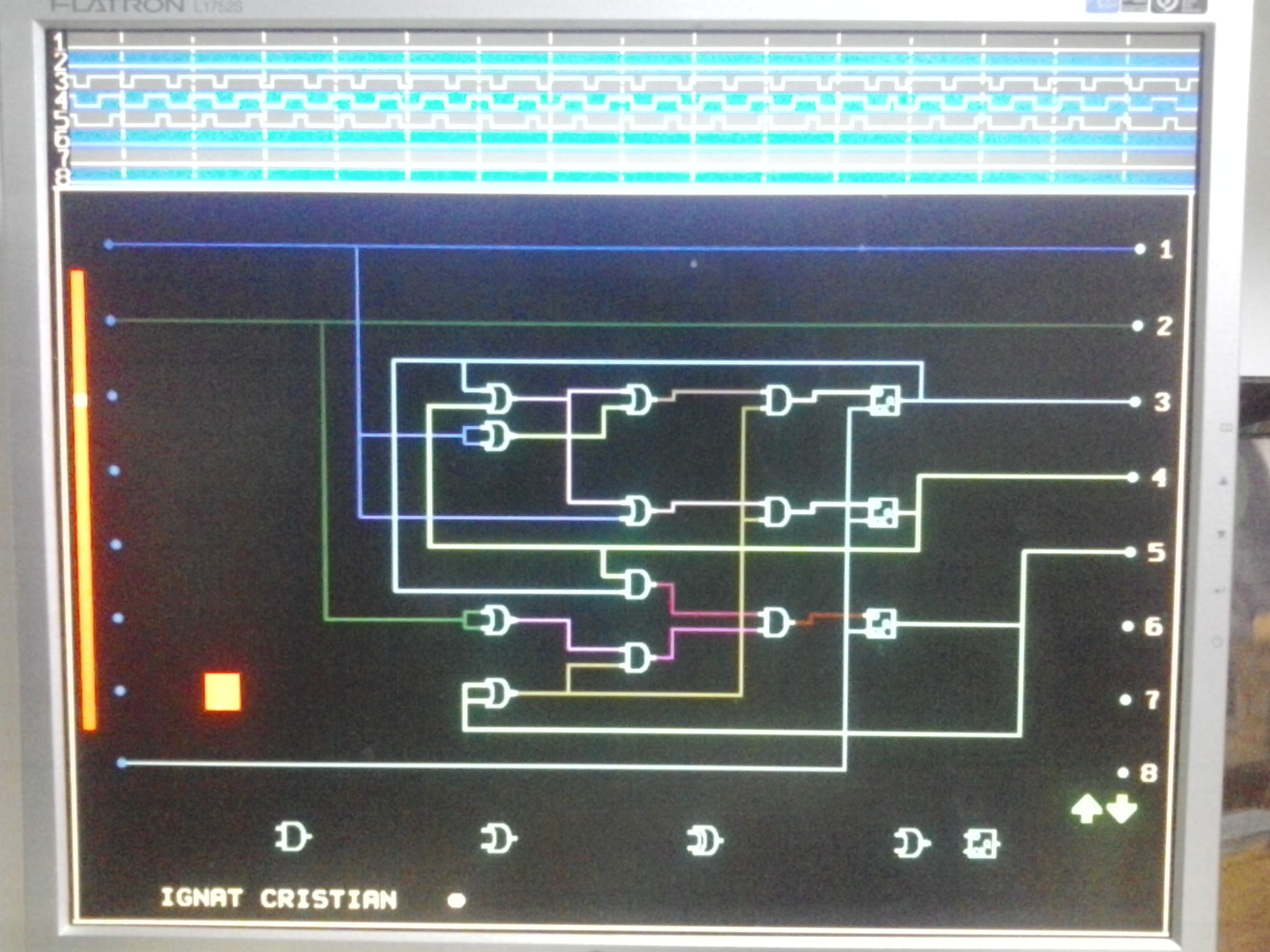
Hi,

I am a contestant of digilent contest, and I need a feedback for my
project.

A short description is:

This project implements a digital circuit design tool, as the name says,
in FPGA. The FPGA board is connected directly on a monitor and a mouse.
The user should use this project to create a digital schematic, and he
could check the output signals on a logic analyzer which is included in
the project.

Here we have two working modes: directly mode, using a mouse which is
connected directly on FPGA board, and second mode, using PC. In second
mode, user should use Xilinx ISE to create a schematic, and after
executing a command, some data are transferred to FPGA via RS232
communication and the schematic is created automatically.

FPGA part is implemented in VHDL and in second mode, the data prom
Xilinx ISE schematic is processed with Visual Basic Script.

You can watch on a example movie on the link:
https://www.youtube.com/watch?v=G0QwzR-WGa0

Thank you
Attached files:
-

2014-01-19_23.28.17.jpg
910 KB
So you are producing graphics on the VGA, which represents Logical
ciruits? Funny idea, but what is it for? Usually this very fast
VGA-strategy makes only sense, if there is high movement in the Image
just like Scrolling or 3D-image Rotation. Whith static Images like
electronic schematics this is of no benefit or did I miss something?

In how far can the electronic circuit be manipulated? Can I place
something different than shown in the Screen?

From the complexity of the Task, you did a godd work - but from the
meaing und usability I'd rate it not so high.
This is a real time implementation. This is an easy way to check a
schematic and to see the result at once. I don't like to use the
simulation programs, and this project can help the students to learn
more easier.

On the monitor, for this project only the schematic and the output
signals can be displayed.
Please log in before posting. Registration is free and takes only a minute.
Existing account
Do you have a Google/GoogleMail account? No registration required!
Log in with Google account
Log in with Google account
No account? Register here.