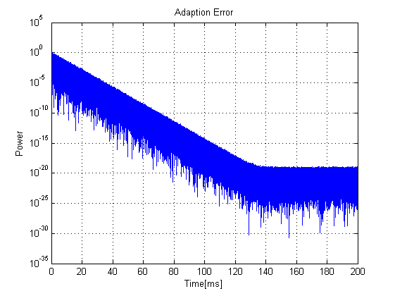
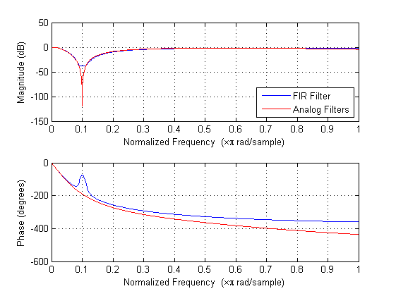
Dear community,

for further work in active noise control with LMS algorithm in first
step I need to identify the secondary path of the system which contains
maintainly an analog low pass and two analog band stop filters.

My problem is that the identification doesn't work exactly. The
frequency response of my adaptive filter doesn't meet the response of
the analog filters, most notably in phase (q.v. figure
frequency_responses). When I use this approximated path for the active
noise control, the whole system doesn't work very well.

However the adaption of the secondary path reaches a converged state
with an error power of about 10^(-20) (q.v. figure adaption_error)
which, I think, is a good result.

For the adaption I use a 100-tap FIR filter with an LMS-adaption step
size of mu=0.00025 and a noise source (q.v. system_view.html).

Can anyone help me by tuning the algorithm for better results?

Maybe it's even impossible to approximate an analog path with an FIR
filter exactly?

Thank you very much.

Rainer
Attached files:
-

adaption_error.png
3.5 KB -

frequency_responses.png
2.8 KB
You will never be able to exactly identify an analog (IIR) path with an
FIR filter. Your filter is quite short, did you try a longer filter? Can
you show the impulse response?
Attached files:
-

impulse_response.png
2.2 KB
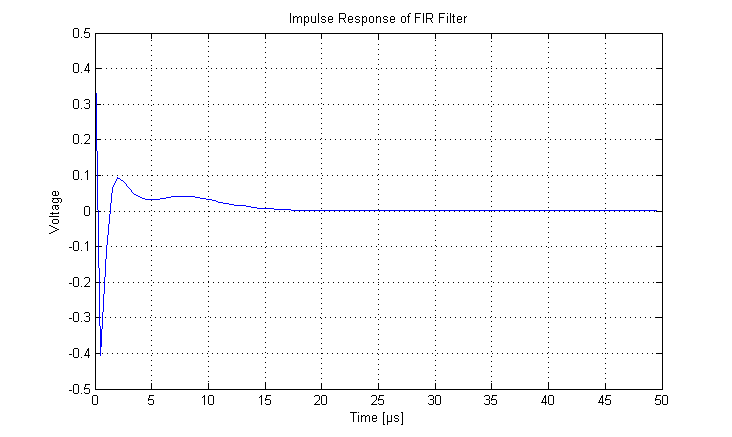
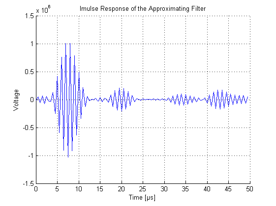
Thank you for reply.

In this figure you can see the impulse response of the approximating FIR
filter.

After the 40th tap, which is at 20us, the coefficient values of the FIR
filter are pretty small. So I think increasing the filter order would
not improve performance.

Maybe I should also decrease the step size mu of the algorithm for a
smaller remaining error. I will try to work this out.
Your impulse response seems to be long enough to the right, but not to
the left. You need a few anticausal taps. Delay the output signal by a
few samples, until you get a few real zero taps at the beginning of the
impulse response, then you will be able to identify the system much
better. Of course, you can't use anticausal filters in real life (which
is why ANC doesn't really work that well).
Attached files:
-

frequency_responses.png
3 KB -

impulse_response.png
3.1 KB
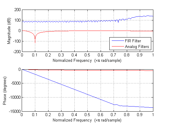
I don't know what to do...
When I delay the output of the FIR filter by only one tap the
LMS-algorithm doesn't work anymore (q.v. figures).
So did I get your advise wrong?
I tried some positions for the delay taps. When I delay the input of the
analog filters the phase of the FIR filter rises. Now I tried some
numbers of delays, at one number of taps the phase of the analog filters
is met, but the magnitude got worse. Also in the implulse response there
didn't come up zero taps at the beginning yet.
Is that right or is there another way?
You need to add an artificial delay in (before/after) the system that
you want to identify.
1 | --------> system ----> delay ----->+----> |
2 | | -^ |
3 | | | |
4 | |----- > adaptive filter--------| |
Thanks for your help. Those anticausal steps do work. In real I also
will have delay taps caused by an DA and an AD converter.

Meanwhile I figured out another way:
I send one single pulse to the secondary path. At the sink the impulse
response sampled with the frequecy of the FIR filter is measured.
That works very good, too. And it's much faster.

Now my FxLMS algorithm does work. Thank you for your help.
Please log in before posting. Registration is free and takes only a minute.
Existing account
Do you have a Google/GoogleMail account? No registration required!
Log in with Google account
Log in with Google account
No account? Register here.