-
Article
STM32
Sie teilt sich in mehrere Dokumente auf. Als Beispiel der Dokumentation soll stellvertretend der STM32F103RC genannt werden. Die Seite von ST beinhaltet alle nötigen Informationen passend zu diesem Prozessor. Diese Dokumente von ST beschreiben den Controller: Im STM32F103xC/D/E Datasheet sind die speziellen
stellt den Port :2000 für GDB zur Verfügung. Stlinks können, so man sich Programmierzugang zu dem STM32F103 des Stlinks beschaffen kann, auch mit BMP Firmware umgeflasht werden. Andere Programmiersprachen. Mecrisp-Stellaris, eine native Forth-Implementation für ARM Cortex M0/M3/M4. Es werden bereits mehrere
-
Article
WordClock mit WS2812
Varianten Controller style="width:30%" | Dateiname style="width:40%" | Eigenschaften WordClock12h STM32F103 BluePill wc12h-stm32f103-ws2812-grb.hex WS2812 mit Farb-Reihenfolge GRB (Standard) wc12h-stm32f103-ws2812-rgb.hex WS2812 mit abweichender Farb-Reihenfolge RGB wc12h-stm32f103-sk6812-rgb.hex SK6812
SK6812 RGBW mit zusätzlicher weißer LED wc12h-stm32f411ce-25-apa102.hex APA RGB LEDs WordClock24h STM32F103 BluePill wc24h-stm32f103-ws2812-grb.hex WS2812 mit Farb-Reihenfolge GRB (Standard) wc24h-stm32f103-ws2812-rgb.hex WS2812 mit abweichender Farb-Reihenfolge RGB wc24h-stm32f103-sk6812-rgb.hex SK6812
-
Article
CAN
Schnittstelle STM32F072 : 1 CAN Schnittstelle Cortex M3 Core - STM32 F1 series of mainstream MCUs STM32F103 : 1 CAN Schnittstelle STM32F105 : 2 CAN Schnittstellen STM32F107 : 2 CAN Schnittstellen - STM32 F2 series of high-performance MCUs STM32F205 : 2 CAN Schnittstellen STM32F207 : 2 CAN Schnittstellen
-
 Image
Image
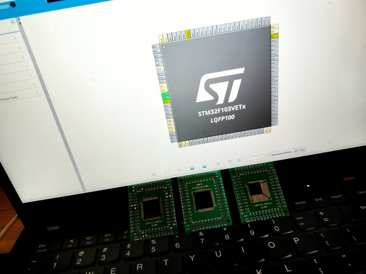
Laptop mit STM32F103VETX Chip-Abbildung und drei Mikrocontrollern
STM32F103VETX LQFP100
-
Article
NIC
angeschlossen. Diese blinkt dann bei der Ausführung des Programms. Um die board-interne blaue LED eines STM32F103-Mini-Development-Boards anzusprechen, muss der Port GPIOA durch GPIOC ersetzt und die Pinnummer auf 13 geändert werden, denn hier ist die LED an Pin C13 angeschlossen. Durch Anwendung der Funktion
Bei einem mit 85MHz getakteten STM32F401RE sind es noch knapp 200.000 Schleifendurchläufe, beim STM32F103 mit 72MHz-Takt ca. 180.000 Durchläufe. Das Programm kann aber noch stärker vereinfacht werden. Jetzt verzichten wir auf die Variable "millis": Als Funktionsparameter können also auch Rückgabewerte
-
Article
KiCad
Hier sollen geprüfte Bibliotheken gesammelt werden. Bitte angeben, wer die Prüfung gemacht hat. STM32F103xx (LQFP64) Schaltplansymbol erstellt/geprüft: Dominik C.; Marko S. Bei der STMF103xx fehlt glaub ich der Portpin PD2 :) Grüße :) Sonstige Bibliotheken im Netz. Die Einträge hier sind nach KiCad-Bibliotheken
-
Article
Speicher
Nutzung irgendwann leer ist und nicht mehr als Backup dienen kann. Einige Mikrocontroller, namentlich STM32F103, bieten einen gesonderten Batterieanschluss U BAT , der dem Anwender sowohl die Diodenentkopplung als auch die Wurstelei mit der Zustandsmeldung erspart. Leider drehen sich die meisten Errata um
-
Article
ARM-ASM-Tutorial
recommended to use the same components. Microcontroller selection. For the microcontroller, an STM32F103C8 or STM32F103RB by STMicroelectronics will be used. Both controllers are identical except for the flash size (64 KiB vs 128 KiB) and number of pins (48 vs 64). These controllers belong to ST’s “
customary to name the linker script after the controller they are intended for, so create a text file “stm32f103rb.ld” or “stm32f103c8.ld” with the following contents: Example name: “LinkerScriptSimple” This is this minimum viable linker script for a microcontroller. If you are using a STM32F103C8, replace
-
Article
USB-Tutorial mit STM32
werden, um dies auch für einfache Hobby-Projekte zugänglich zu machen. Als Mikrocontroller wird der STM32F103RB genutzt, welcher native Unterstützung für USB-FullSpeed-Devices bietet. Um das Verständnis für die Hardware zu fördern und die komplexe und eher undurchsichtige USB-Bibliothek des Herstellers selbst
USB High Speed (480 MBit/Sec). Hier wird ein Controller mit der einfachsten Variante gewählt, der STM32F103RB. Dieser ist beispielsweise auf dem Olimexino-STM32 zu finden, im Folgenden wird dieses als Grundlage für die Beispiele genutzt. Der auf den günstigen Blue Pill-Boards zu findende STM32F103C8 kann
-
Article
STM32F103C8T6 STM32 Billig Board
], 2.73€ [12.10.2024]) ein minimalistisches STM32-Board. Auf Ebay im Suchfeld Suchfeld einfach "STM32F103C8T6" eingeben. Eckdaten: STM32F103C8T6 64k Flash (viele C8 besitzen in wirklichkeit 128k Flash), 20k RAM Micro-USB, ISP Header (SWDIO) 8MHz System-Quarz, 32.768kHz RTC Quarz BOOT0/BOOT1 Jumper RESET
USB-Buchse kann man es sicher wie einen Arduino Nano direkt vom PC aus programmieren. Doch halt: Der STM32F103C8T6 kostet bei ST schon in 1000er Stückzahlen 3.40€. Auf den Boards ist also kein STM32F103C8T6 drauf sondern irgendeiner seiner chinesischen Clone oder gleich gar kein Chip im Gehäuse. Ausserdem
-
Article
IRMP
STM32 STM32F4xx (getestet auf STM32F401RE/F411RE Nucleo, STM32F4 Discovery) STM32F10x (getestet auf STM32F103C8T6 Mini Development Board) STM32 mit HAL-Library (NEU!) STM8 STM8S103F3 TI Stellaris LM4F120 Launchpad (ARM Cortex M4) ESP8266 (NEU!) ESP8266-EVB TEENSY 3.0 (NEU!) MK20DX256VLH7 (ARM Cortex-M4 72MHz
-
Article
STECCY
Kabel mit dem BlackBoard verbunden werden. Schema: Hier werden die Zeilen/Spalten wie folgt an den STM32F103 auf einem BluePill-Board angeschlossen: Spalten Zeilen --- --- --- --- --- --- --- --- --- --- --- --- --- Z80 D0 D1 D2 D3 D4 A11 A10 A9 A12 A13 A8 A14 A15 STM32F103 PB3 PB4 PB5 PB6 PB7 PA3 PA2 PA1
-
Article
Tutorial - Aufbau WordClock mit WS2812
eingebaut nur wenn Spannungsabschaltung eingebaut miniatur = Löten des Mini-Dev-Board-Shields v4 für STM32F103 = miniatur Rechts seht Ihr ein Mini Shield V4 bestückt für STM32F103, DS3231/RTC Echtzeituhr, AMS1117/Spannungsregler, LDR/Fotowiderstand und DS1820/Temperatursensor. Die Anschlußleisten rechts und
die IP-Adresse des ESP8266 ist wesentlich größer als 10msec oder setzt für mehrere Sekunden aus STM32F103C8T6 Mini-Development Board. Falsche STM32 Software geflasht, mögliche Symptome: Die LED PC13 des STM32F103 Board leuchtet nach dem Start nicht Der WebServer ist erreichbar, allerdings wird das EEPROM
-
Article
Und noch 'ne Nixie-Uhr
Wiki PFW551 Datenblatt Referenzen. MP2103-Stick mit ARM7 (LPC2103) MP-Stick mit ARM Cortex-M3 (STM32F103CBT6)
-
Thread
Embeetle IDE free for all users, now supports Blue Pill and more.
Pill board. The STM32 Blue Pill is a 32-bit Arduino-compatible development board that features the STM32F103C8T6. A member of the STM32 family of ARM Cortex-M3 core microcontrollers. The STM32 Blue Pill board has nearly all the capabilities of the Arduino module but at a lower price. Check out Embeetle
-
Article
IRMP - english
PIC18F4520 STM32 STM32F4xx (tested on STM32F401RE/F411RE Nucleo, STM32F4 Discovery) STM32F10x (tested on STM32F103C8T6 Mini Development Board) STM32 with HAL library (NEW!) STM8 STM8S103F3 TI Stellaris LM4F120 Launchpad (ARM Cortex M4) ESP8266 (NEW!) ESP8266-EVB TEENSY 3.0 MK20DX256VLH7 (ARM Cortex-M4 72MHz)
-
Thread
STM32F103 math package
This is the overview of STM32F103 newly updated. It includes the clock tree of STM32F103 and more, hope it helps. https://www.embedic.com/technology/details/stm32f103
This is the overview of STM32F103 newly updated. https://get-9apps.com/web/ https://get-cartoonhd.com
-
Thread
STM32 ADC & DMA corrupted Values
Are you using an STMF103C8xx or STM32F103CBxx? I am asking because the web is full of negative reports about fake products with wrong data transferred by DMA.
.. i have to check. whats the outcome if there is an error? >Are you using an STMF103C8xx or STM32F103CBxx? I am asking because the >web is full of negative reports about fake products with wrong data >transferred by DMA. the mcus are from the STM32F0xx and STM32G4xx Family. they should be
-
Thread
connected DIN MIDI Out cable disturbs encoder
Hey, i am currently working on a MIDI related project utilizing a STM32F103 and a Hex Buffer (74HC365). I have the following problem: reading the encoder works fine (handled via interrupts) until i connect a midi cable to the midi out port, then the readings of the encoder
-
Article
MINOS
externer Pullup-Widerstand vorgesehen ist, muss kein interner Pullup-Widerstand aktiviert werden. Beim STM32F103 Mini-Development-Board gibt es bis auf den RESET-Taster keinen weiteren Taster auf dem Board. Wir können aber zum Beispiel einen Taster an PA6 anschließen, so dass er gegen GND schaltet. Den externen
: Einschalten der Board-LED, sobald die blaue User-Taste gedrückt wird, sonst ausschalten. Beim STM32F103 Mini-Development-Board gibt es eine blaue LED auf dem Board. Sie ist an PC13 angeschlossen. Allerdings muss diese gegen GND geschaltet werden, damit sie leuchtet. Sie ist also "active low" - im Gegensatz
-
Article
FY6900
wird, geschätzt 40°C. Das FPGA bleibt auch entspannt lauwarm. Hinter der Frontplatte werkelt ein STM32 F103C8T6. Ein paar Bilder gibt es hier und hier. Fazit. Der Signalgenerator hat ein sehr gutes Preis/Leistungsverhältnis und ist auch überaus leistungsstark. Die Fernsteuersoftware ist sehr schlecht,
-
Article
LCS-1M - Ein einfaches, preiswertes, mikrokontrollergesteuertes Zweikanal-Oszilloskop zum Selberbauen
available for self-building sets or as product. Some examples are: DSO 138, 1 Channel, 200kHz Bandwith, STM32F103 internal 12 Bit ADC used. DSO 150, DSO 062, DSO 202 has 2 Channels. Downloads. Scope homepage: Hardware: Schematic: Layout: Bill of materials: Download of firmware and PC software: Siehe auch. Article
-
Thread
STM32F103VET6 und CH340R
I have a problem with my PCB. I recieved it a few days ago and it is already completly presoldered. If i connect it via USB-TYPE B to my pc it is showing me nothing in device menager.... The CH340G should be visible to be able to programm it via usb.... If i connect it via micro-usb unknown device is popping up. But that does not help me :). I have added the schematic. Hope someone can help me.
-
Thread
Wordclock stopped working
board_led_init... button_init... timer2_init... wpsbutton_init... Version: 2.9.5 Hardware: STM32F103 Display: WC12h LEDs: WS2812 GRB rtc is online eeprom is online ws2812: external pullup detected eeprom is online current eeprom version: 0x00000000 updating EEPROM to version 0x00020900..
-
Thread
STM32 HAL Delay too slow
Hi, I recently started with an STM32F103C8T6 on a bluepill board. I am using SW4STM32 on Windows 10. When writing a program that blinks an LED on PC13 with the standard peripheral library and implementing my own SysTick_Handler and
own firmware. I give you a hint, how to do: https://www.mikrocontroller.net/attachment/316790/STM32F103C8T6.ZIP Just have a look into it - and use what you want if you are interested. btw: the binary in this archive should also work on a blue-pill board. W.S.
-
Thread
Which microcontroller to use and how?
you want something larger then I would recommend any ARM based microcontroller, for example the STM32F103 series which is available in different sizes). Regarding your current monitor: If you measre the current between power supply and voltage regulator then you measure the current consumption of
recommend to control the MAX5217 for the best results and more accurate? price is not important. the STM32F103 ?
-
Article
IRMP auf STM32 - ein USB IR Empfänger/Sender/Einschalter mit Wakeup-Timer
2018 Jörg Riechardt Einleitung. Für ca. 4 - 8 € kann man auf ebay einen ST-Link Emulator oder ein STM32F103 Board kaufen, meistens in China hergestellt. Auf den darauf befindlichen STM32F103 Mikrocontroller wird eine Open Source Firmware mit vielen Funktionen geflasht. Funktionen. Anschluss über USB meldet
hilfreich, um mit dem STM32F105 anfangen zu können. Andrew Kambaroff für seinen USB-HID für den STM32F103. [3] Seine Arbeit war hilfreich, um mit dem STM32F103 anfangen zu können. Ole Ernst für Code Review, Linux Makefile und Linux Download-Auspack-Patch-Skript, viel bessere Makro Implementierung und
-
Article
UART auf USB
Mikrocontroller enthalten USB-CDC-Beispiele. Tutorial zur Implementierung eines 3-Fach USB-Serial-Adapter mit STM32F103 und CDC sonstige/unbekannt. Das Nokia CA-42 USB Kabel soll auch für 3.3V UART funktionieren Ich habe ein CA-42 USB Kabel Nokia in Betreib, es funzt gut, ich werde demnächst mal die Anschlußbelegung
-
Article
Datei:Debugging STM32F103 USB InitPacket.png
Anzeige des ersten Pakets vom Host beim Debugging einer USB-Anwendung auf STM32F103. Autor: Niklas Gürtler Lizenz: CC BY 4.0
-
Article
Datei:STM32F103 USB Buffer Mem.svg
Schematische Darstellung der Struktur des USB-Pufferspeichers der STM32F103. Autor: Niklas Gürtler Lizenz: CC BY 4.0
-
Article
IRMP auf STM32 - Bauanleitung
stlink.git cd stlink ./autogen.sh ./configure ./make ./st-flash erase ./st-flash --reset write /IRMP_STM32/F103C8/firmware.bin 0x8000000 In manchen Fällen ist es nötig, zu Beginn des Flashens den ST-Link zu resetten. Dazu muss die Stelle im Bild auf Masse gezogen werden und kurz nach Absetzen des Flash Befehls
stlink.git cd stlink ./autogen.sh ./configure ./make ./st-flash erase ./st-flash --reset write /IRMP_STM32/F103C8/firmware.bin 0x8000000 In some cases it is necessary, to reset the ST-Link at the beginning of flashing. You need to pull the marked area in the image to ground and release it shortly after the
-
Article
Datei:Vcc-gnd.com-blue-pill-schematic-stm32f103c8t6.pdf
Schaltplan des blauen STM32F103C8T6 dev Boards von aliexpress, ebay und co. Nennt sich auch "Blue Pill".
-
Article
Benutzer:Mampf
vollständig hinter der Röhre :) keine VFD-Spezialbauteile :) Kurzes Video: Mini-Word-Clock. Benutzt einen STM32F103 Hier noch ein kurzes Video zu V2.0: RGB Moodlight/Clock/Reminder. Spaßeshalber hatte ich mir überlegt, ein RGB Mood-Light zu bauen, da ich dafür einige verschiedene Verwendungszwecke habe. Außer
-
Article
Datei:Mini Shield V4 STM32F103 DS3231 AMS1117 2a.jpg
Mini Shield V4 für STM32F103+DS3231+AMS1117+LDR+DS1820
-
Article
Datei:Mini Shield V4 STM32F103 DS3231 AMS1117 ohne R2 R5.jpg
Mini Shield V4 STM32F103 DS3231 AMS1117 ohne R2 da mit LDR, ohne R5 da kein TSOP
-
Article
Datei:Mini Shield V4 STM32F103 DS3231 AMS1117 3aa.jpg
komplettes Mini Shield V4 mit STM32F103+DS3231+AMS1117+(LDR+DS1820)
-
Article
Datei:Clockmampf.jpg
wordclock auf stm32f103 basis
-
Thread
STM32 Changing PWM Duty Cycle in interrupt handler
aSma>> wrote in post #4970691: > The stm32f103 timer has only 16 bits. I assumed I needed to provide my data as uint32_t as the example from the SDK ( /STM32Cube_FW_F1_V1.4.0/Projects/STM3210E_EVAL/Examples/TIM/TIM_DMA/Src/main.c ) declares
said, I didn't look into DMA before as my initial analysis was it > would need too much RAM. stm32f103 has 20kb RAM. 8 ch * 64 pixel * 24bits/pixel * 1/8 byte/bits = 1.54kb With a 16bit timer you need about 3kb.
-
Article
Datei:STM32F103-Bootloader-2.6.0.png
Ab Version 2.6.0
-
Article
Datei:ESP-12F-an-WC-STM32F103-2.6.0.png
Ab Version 2.6.0
-
Article
Datei:Stm32f103c8t6 blinky.bin
blinky on PC13
-
Article
Datei:STM32F103-Bootloader.png
Anschluss ESP8266 an BOOT0
-
Article
Datei:Wc24h-STM32F103.hex
Version 1.6.1
-
Article
Datei:Wc12h-STM32F103.hex
Version 1.6.1