Guest
#5934018
Hi there,

for a project I want to sample an input signal with an ADC and send the
digitized values via SPI to a microcontroller for further
postprocessing.

My measurement configuration consits of a waveform generator that is
connected to an single-to-differential circuit (DC2622A from Linear
Technologies). The two differential signals are directly connected to an
ADC eval board (EEVAL-AD4001-FMCZ) from Analog Devices. In the later
course I want to connect the ADC directly with a microcontroller from ST
(STM32F767ZI) via SPI. But for test purposes and to see if the hardware
setup is correctly, but for now I am using the SDP-H1 Evaluation Board,
which is recommended from Analog Devices for the ADC.

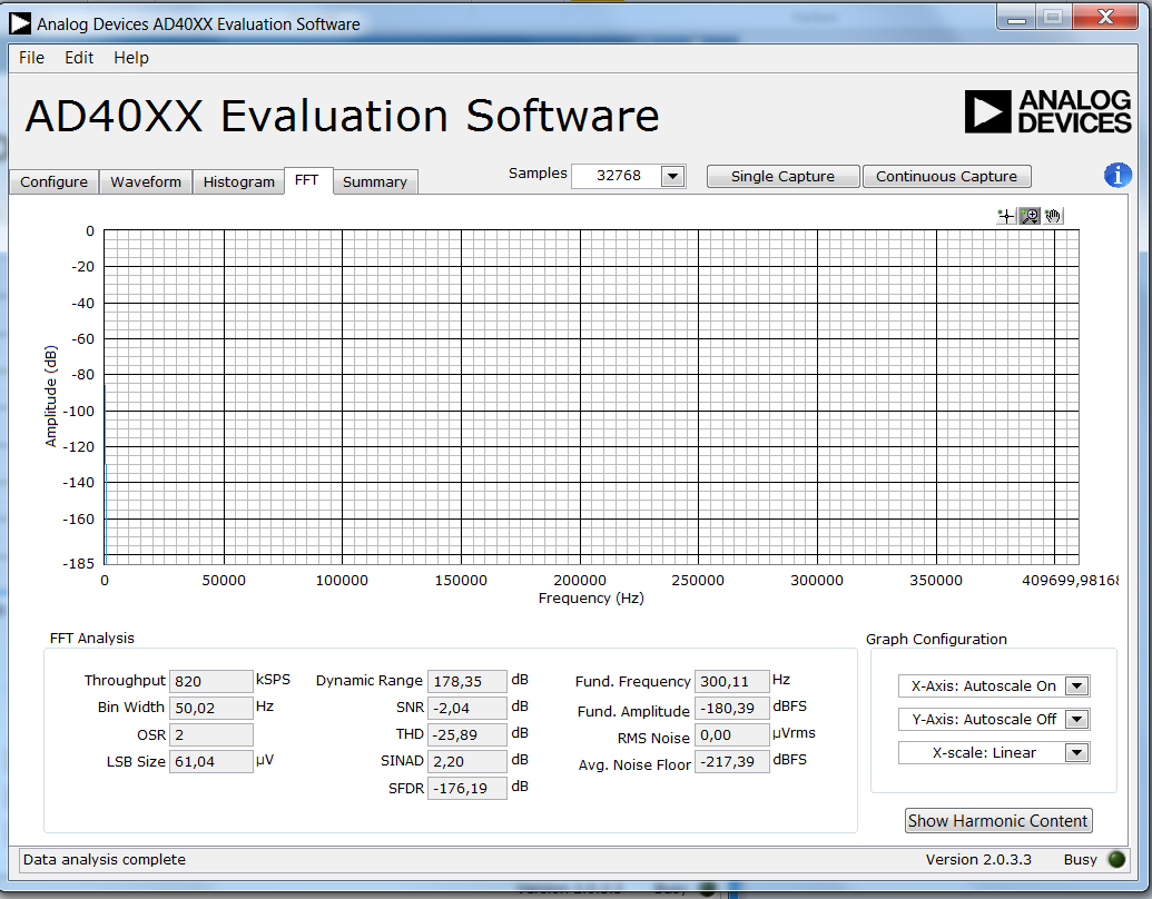
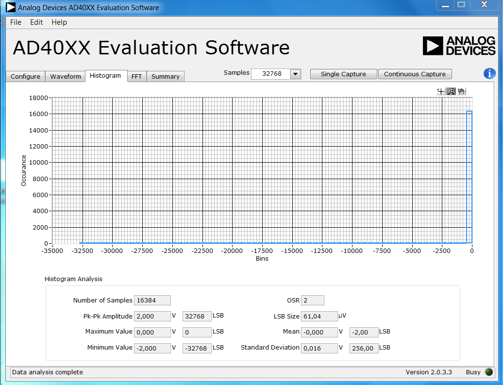
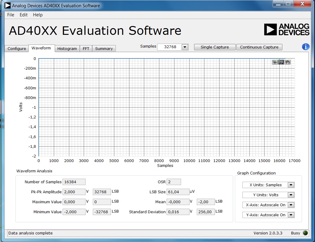
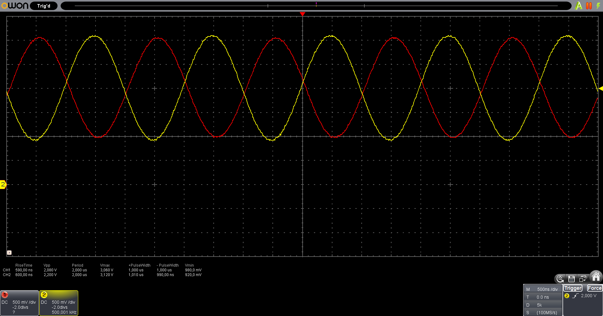
My problem is, that an input signal like a sinussignal with 2 volt
peak-to-peak voltage occurs at the the testpoints IN+ and IN- as
expected (two sinussignals with one signal phase-shifted by 180
degrees). Nevertheless, if I run the evaluation software there are two
problems. On the one hand I am expecting a sinussignal at the waveform
tab, but there is nothing but a straight line at 0 volt and a short peak
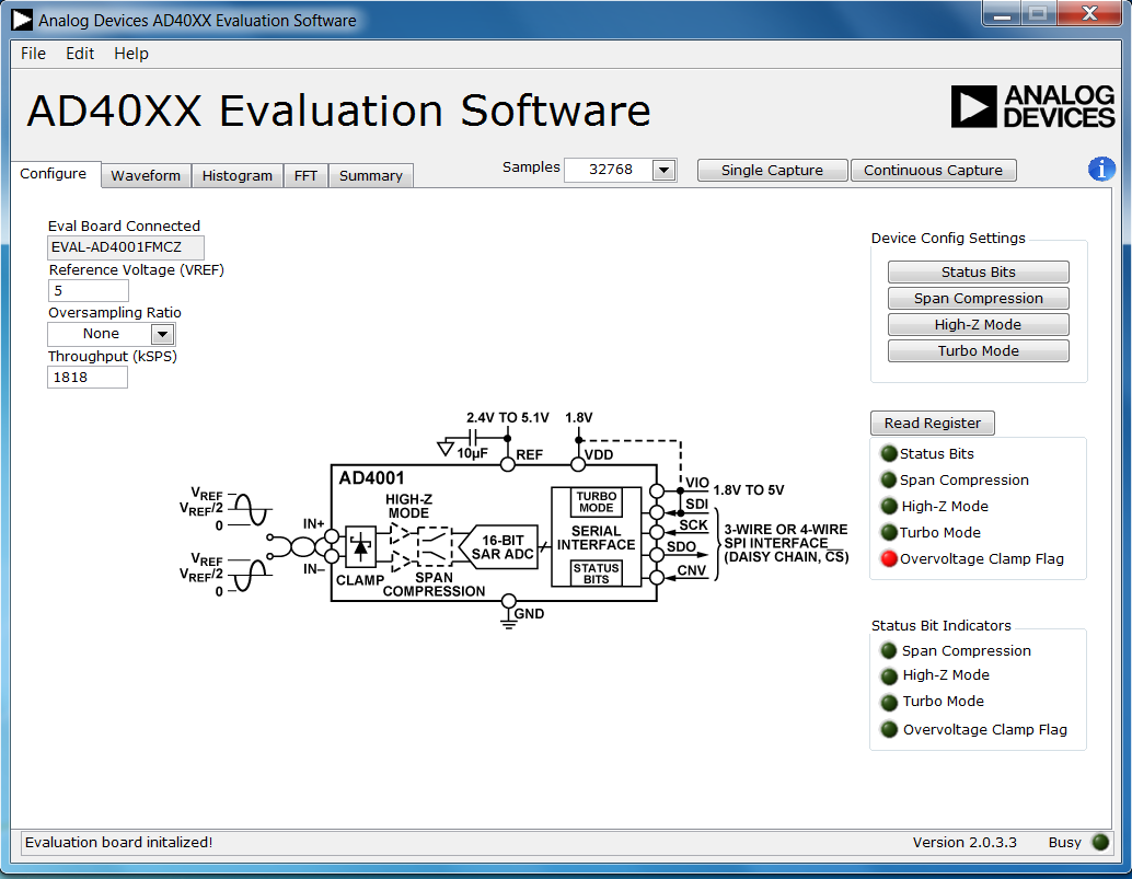
to -5 volt. And on the other hand, I am always getting an overvoltage
indicator if i read the status bits. This only dissappears if i set all
the other status bits like High-Z, Span Compression and Turbo mode,
which does not make sence to me. Does anybody have an advice or know
where my mistake is?
Attached files:
-
 FFT.png
(87 KB)
FFT.png
(87 KB)
-
 Histogramm.png
(78 KB)
Histogramm.png
(78 KB)
-
 Waveformanalysis.jpg
(280 KB)
Waveformanalysis.jpg
(280 KB)
-
 ConfigurationOV.png
(120 KB)
ConfigurationOV.png
(120 KB)
-
 ConfigurationwithoutOV.png
(99 KB)
ConfigurationwithoutOV.png
(99 KB)