Hi all,

I need some help. I am coding for a 32 bit adder using two 16 bit adders
in Time Division Multiplexing using Moore State Machine such that the
lower 16 bit adder results the lower 16 bits of sum and then in next
clock cycle, the upper 16 bits are added by the same adder such that the
carry generated by the lower 16 bit sum becomes the carry in for the
upper 16 bit addition. When I simulate, for the upper 16 bit addition,
the simulation goes in a loop (as desired) but it continues there
continuously till 10000 iterations and then I get an error :

"FATAL_ERROR: Iteration limit 10000 is reached. Possible zero delay
oscillation detected where simulation time can not advance."

How to write code for feedback circuit without reaching the iteration
limits? (This logic is part of a system whose code files are too huge
and complicated)
Rohan N. wrote:
> "FATAL_ERROR: Iteration limit 10000 is reached.
Its fairly simple: you have a combinatorial loop in your code. Try to
synthesize your code. The synthesizer will report a "combinatorial loop"
or at least several "latches".
Try that with Google translator, its German:
http://www.lothar-miller.de/s9y/categories/36-Kombinatorische-Schleife

> (This logic is part of a system whose code files are too huge and
> complicated)
So post "this logic". A combinatorial loop usually its fairly easy to
recognize, even when it is a gated combinatorial loop (and therefore
reported as a latch by the synthesizer)...
Attached files:
-

infinite_loop.png
180 KB
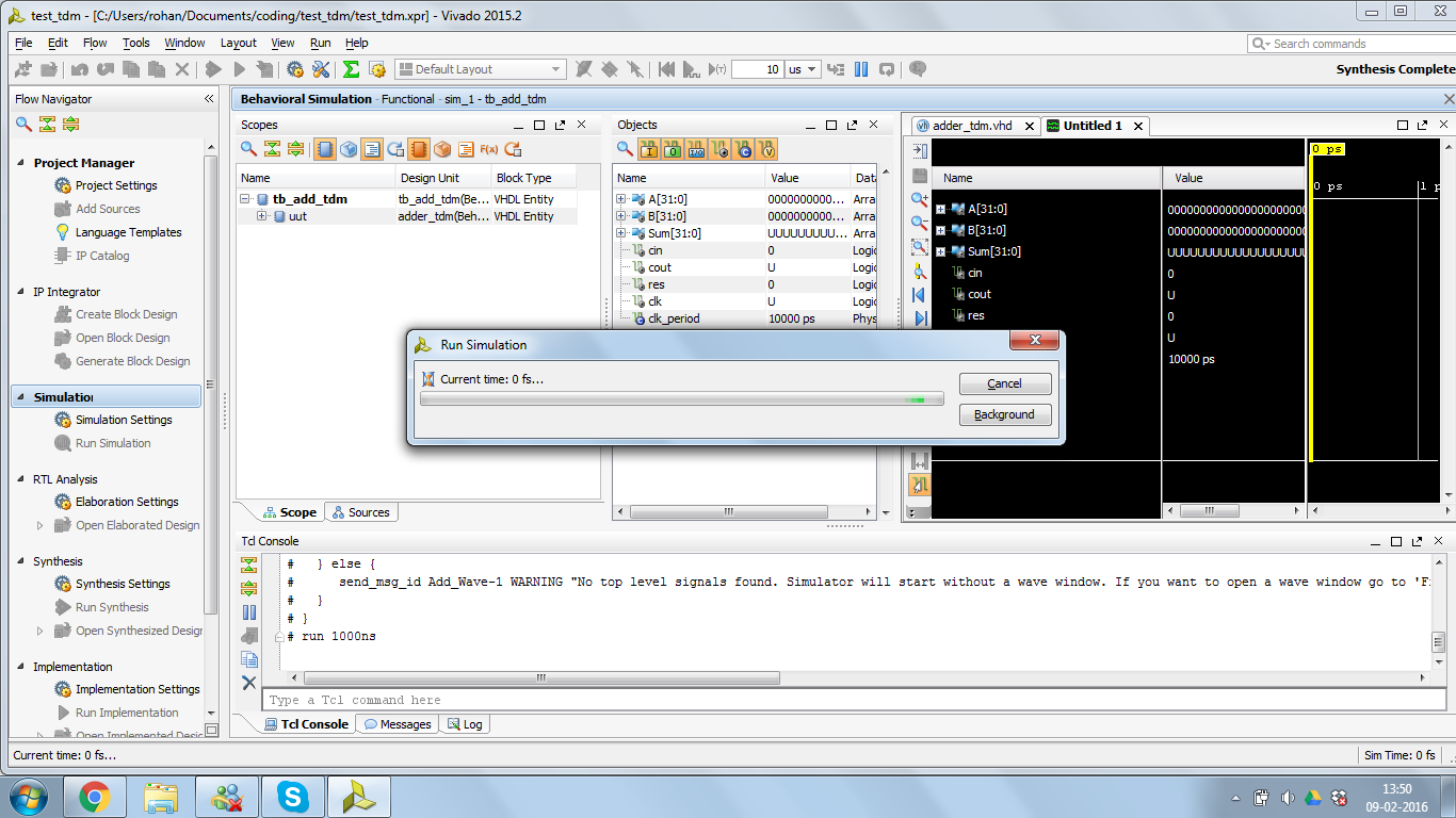
Hi,

Thanks for the reply and the link. I made some changes but now the
simulation goes to infinite loop. It shows the message - Current time :
0 fs. Please see the code files for this logic attached with the
screenshot of simulation message. You can also try to simulate the code
at your end with the files attached. Please let me know the cause of
this and also suggest meathod to fix it.

Thanks and regards,
Rohan Narkhede
Maybe this loop does not what you want it:
1 | for i in 1 to N-2 loop |
2 | c(i+1) <= g(i) or (p(i) and c(i)); |
3 | end loop; |
When you unroll it then you will have this here:
1 | c(2) <= g(1) or (p(1) and c(1)); |
2 | c(3) <= g(2) or (p(2) and c(2)); |
3 | c(4) <= g(3) or (p(3) and c(3)); |
4 | c(5) <= g(4) or (p(4) and c(4)); |
5 | c(6) <= g(5) or (p(5) and c(5)); |
6 | c(7) <= g(6) or (p(6) and c(6)); |
And now you must be aware of the behavioural of signals: they don't
change their values throughout a process. Finally at the end of the
process the new value is taken over.
So you ca write down this loop without any change in behaviour(!!!)
like this:
1 | c(7) <= g(6) or (p(6) and c(6)); |
2 | c(2) <= g(1) or (p(1) and c(1)); |
3 | c(3) <= g(2) or (p(2) and c(2)); |
4 | c(6) <= g(5) or (p(5) and c(5)); |
5 | c(4) <= g(3) or (p(3) and c(3)); |
6 | c(5) <= g(4) or (p(4) and c(4)); |
Or this very similar way:
1 | c(7) <= g(6) or (p(6) and c(6)); |
2 | c(6) <= g(5) or (p(5) and c(5)); |
3 | c(5) <= g(4) or (p(4) and c(4)); |
4 | c(4) <= g(3) or (p(3) and c(3)); |
5 | c(3) <= g(2) or (p(2) and c(2)); |
6 | c(2) <= g(1) or (p(1) and c(1)); |
Is that ok for the functionof your adder?
Or did you expect something like a "propagating carry"?

A hint: you must use a local variable for that carry.
:
Edited by Moderator
Attached files:
-

adder_tdm_no_funtion.png
29 KB
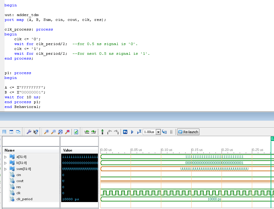
ISE in Version 13.2 says:
1 | WARNING:HDLCompiler:1369 - "C:/Projekte/FPGA/adder_tdm/tb_add_tdm.vhd" |
2 | Line 45: Possible infinite loop; process does not have a wait statement |
And indeed: a process without wait will "run" forever. Add a "wait":
1 | p1: process |
2 | begin
|
3 | |
4 | A <= X"FFFFFFFF"; |
5 | B <= X"00000001"; |
6 | wait for 10 ns; |
7 | |
8 | end process p1; |
Or remove the process:
1 | --p1: process
|
2 | --begin
|
3 | |
4 | A <= X"FFFFFFFF"; |
5 | B <= X"00000001"; |
6 | --wait for 10 ns;
|
7 | |
8 | --end process p1;
|
Both will be fine...

However the design will not run. But you will be able to simulate it.
Hi Lothar,

Thanks a lot for suggestion. By adding a delay, I am able to simulate
the code.

But to run this logic, expanding the for loop (as stated in previous
thread) may not be desired as I want to use this cla as generic.(correct
me if I am wrong)

I am planning to add a 1 bit register in the feedback loop - between
carry out of adder, cout_fdbk and the mux_one and controlled by control
unit. The control unit may introduce a new state for this. Does this
idea makes some sense? or there could be a better approach for this?

Thanks and regards,
Rohan
Rohan N. wrote:
> Does this idea makes some sense?
Of course you will need a 1 bit register to memorize the carry out of
the "first" 16 bit addition. But thats a extremely minor aspect of a
problem.

> But to run this logic, expanding the for loop (as stated in previous
> thread) may not be desired as I want to use this cla as generic.(correct
> me if I am wrong)
Hopefully you got the point: its alle the same!!!
Your loop is the very same like may "unrolled" loops and as my
"shuffeled unrolled" loops. And none of them will work as you expect it.
You need a variable for that "immediate" carry propagation inside a
process!

> or there could be a better approach for this?
I can see no need for such a "handmande" adder-construct. Why don't you
just use the '+' sign?

Ok, one step back...
Rohan N. wrote:
> I am coding for a 32 bit adder using two 16 bit adders in Time Division
> Multiplexing using Moore State Machine such that the lower 16 bit adder
> results the lower 16 bits of sum and then in next clock cycle, the upper
> 16 bits are added by the same adder such that the carry generated by the
> lower 16 bit sum becomes the carry in for the upper 16 bit addition.
Split up that problem in smaller problems: first design your "handmade
16-bit-adder". Write the adder module and write a test bench to simulate
exactly and only that adder module.
When it runs design your "handmande multiplexer"(**). Then write a test
bench to simulate that multiplexer only.
When that runs start with the overlying FSM that controls the whole
thing. Use the 2 function proved modules "handmade adder" and "handmade
multiplexer" in that FSM module. Then write a test bench to check the
behaviour of the whole thing. Thats the way to design the whole thing...

(**) a multiplexer in vhdl can be written in one simple line of code
like that:
1 | result <= inputA when selA else inputB; |
:
Edited by Moderator
Please log in before posting. Registration is free and takes only a minute.
Existing account
Do you have a Google/GoogleMail account? No registration required!
Log in with Google account
Log in with Google account
No account? Register here.