Hello,

I have a camera with a micro controller STC15F2K60S2. My camera was
blocked and I'd like to enter the bootloader. Then I connected a USB-TTL
adapter to the following pins: Txd / 3.1, Rxd / 3.0, VCC, GND. But under
the Putty software serial port I see no bootloader at boot of the
camera.

Do I adapateur well connected to the microcontroller, there is a setting
to do?
Can you help me ? Thank you.
Why do you want to enter the bootloader? Do you have a kind of
firmware-update and want to install it?

For the serial connection: did you check the connection by shorting RxD
and TxD on your adapter - just to check, if the connection between putty
and those pins is working?

In most cases the boot loader is only entered, when some condition is
met, e.g. a particular port pin is in a expected state (hi or lo) during
reset or so. And then the autobaud procedure should start, which expects
a predefined character sent by the PC to the bootloader. Without meeting
all of this conditons, you probably will never see the bootloader. So I
suggest to read the manual of the µC.

W.S.
Thank you for answering,

I would like to access the bootloader because I transfered the wrong
firmware for a camera.

So I'd like to enter the bootloader to debug the microcontroller. But I
can not.

If I shorting between RX and TX that will I see in PUTTY?

I looked at the documentation, but I see nothing that speaks bootloader:
http://www.stcmicro.com/datasheet/STC15F2K60S2-en.pdf

Thank you.
Hi,

I reverse engineered the bootloader/BSL protocols of STC chips.

The bootloader on STC 8051 chips has to be triggered on power-on reset
with a sequence of pulses on the UART RX pin. It is also possible to set
an option that disables the bootloader unless two pins (which ones
depends on the particular chip, see the datasheet) are tied to ground.

If you want to avoid STC's tool, you can use stcgal, which was the
result of all my reverse engineering:

https://github.com/grigorig/stcgal
Maybe above was a little bit unclear. Here's some more detailed info.

- After power-on reset (soft reset or reset pin doesn't work) the MCU
listens for a falling edge on the RX pin for a short time. If it
encounters it, the bootloader is entered.
- The pindetect option locks out the bootloader completely, unless
P3.2/P3.3 or P1.0/P1.1 (depending on model) are pulled low. The falling
edge on power-on reset is still required!
- Both STC's tool and stcgal take care of the "pulsing" to generate the
falling edge by sending a stream of 0x7F bytes over UART until the MCU
responds.
Attached files:
-

LQFP44.jpg
130 KB

Can you tell me what the Rx UART pin on my MCU (P3.0?)? and what are the
two pins that disable the bootloader to see if this is not the case on
my pcb.

How to see stc isp tools on the bootloader?
I managed mcu check with stc isp but only occasionally. Sometimes I can
not communicate with the MCU. But I do not know why.

Can you tell me summarize what I should do to successfully see the
bootloader, step by step.

Is it possible that there was nothing in the MCU bootloader?

Do you know where to find and how to flash bootloader?

Attached image of MCU.

Thank you
Attached files:
-

PCBJ2.jpg
250 KB
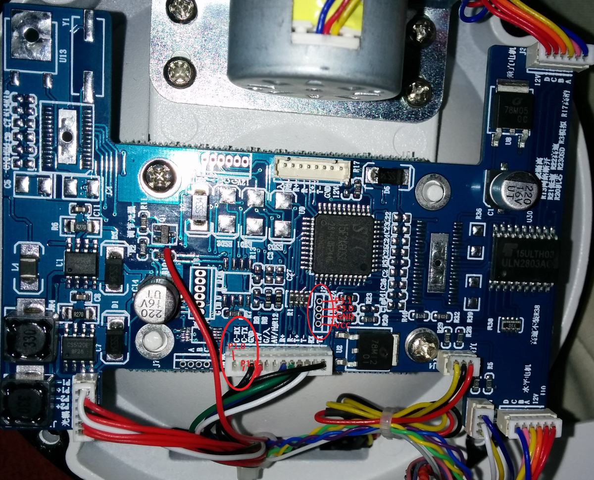
Here is a picture of the PCB with the connections between the chip and
red connectors.

How do I connect usb-ttl to see the bootloader?
Step by step:

Connect GND and USB UART RX to MCU TX and vice versa. Start check or
program in STC-ISP or stcgal, which will then wait for the MCU. Only
then apply power to the MCU's VCC.

In my experience, STC-ISP can be a bit finicky with PL2303 USB UARTs.
stcgal works quite a bit more reliable with those.

Regarding your other questions:

> I managed mcu check with stc isp but only occasionally. Sometimes I can
not communicate with the MCU. But I do not know why.

Good, that probably means you have the connection between UART and MCU
working fine. Try to lower the baudrate, and make sure to always toggle
power when you want to initiate the bootloader.

> Do you know where to find and how to flash bootloader?

The bootloader is preprogrammed in the factory. It cannot be
overwritten. Well, it is not supposed to be, anyway. Maybe there are
undocumented ways to do it, who knows.

> and what are the
two pins that disable the bootloader to see if this is not the case on
my pcb.

Not sure, should be either P1.0/P1.1 or P3.2/P3.3. But check out the
list of device options in STC-ISP for your part, it is documented there.
I followed your advice and I can communicate with the MCU sub-STC ISP:
Checking target MCU ...
  MCU type: STC15F2K60S2
  F/W version: 7.2.2S

Current H/W Option:
  . Current system clock source is internal IRC oscillator
  . IRC frequency: 22.090MHz
  . Oscillator gain is HIGH
  . Wakeup Timer frequency: 37.372KHz
  . Do not detect the level of P3.2 and P3.3 next download
  . Power-on reset, use the extra power-on delay
  . RESET pin behaves as I/O pin
  . Reset while detect a Low-Voltage
  . Thresh voltage level of the built-in LVD : 3.82 V
  . Inhibit EEPROM operation under Low-Voltage
  . Hardware do not enable Watch-Dog-Timer
  . Watch-Dog-Timer pre-scalar : 256
  . Watch-Dog-Timer stop count in idle mode
  . Program can modify the Watch-Dog-Timer scalar
  . Do not erase user EEPROM area at next download
  . Do not control 485 at next download
  . Do not check user password next download
  . TXD is independent IO
  . TXD pin as quasi-bidirectional mode after reset
  . P2.0 output HIGH level after reset

  . MCU type: STC15F2K60S2
  F/W version: 7.2.2S

  Complete !

Against the pin by 1.0 / 1.1 or P3.2 / P3.3 are not shorted. And I still
can not see the bootloader in PUTTY.

Do I have a bridge between two pins on the chip or something else?

Thank you.
What do you mean with "bootloader"? Why do you expect anything to be
visible when connecting over UART with putty? What you see here with
STC-ISP is the bootloader in action.

Of course the firmware that is flashed to the MCU may talk over UART,
but that is a very different thing.
My goal is to have a bootloader with xmodem function and to communicate
with command lines. I wish I could install the original firmware of the
camera via the command lines. At least I can do for stc-isp. But my
firmware is .OV I have no .hex or .bin.
Do you know if there is a bootloader which I could access through a
terminal with which I could use command lines in a STC chip?
By chance you know the .OV format?

Can I retrieve .hex file or .bin file in this firmware? Because in that
case I might be injected with the STC-ISP software?

Thank you.
Can you tell me if it is possible to inject linux.bin and romfs.img by
STC-ISP or stcgal? because I do not see how else without console

My goal is to be able after having to ethernet access to the camera and
install the original firmware.
archi wrote:
> Can you tell me if it is possible to inject linux.bin and
> romfs.img by
> STC-ISP or stcgal? because I do not see how else without console
>
> My goal is to be able after having to ethernet access to the camera and
> install the original firmware.

Sorry, but I have absolutely no idea what you want to achieve here. I
cannot help you. And to be honest, it doesn't look like you know what
you are doing here either. It just doesn't make sense. How does
something Linux come into play? The STC MCUs are 8051 compatible 8-bit
microcontrollers. Linux doesn't work on them.
My camera runs on a Linux kernel, I thought it was stored in the core
STC chip.
Looked at the photo of my pcb above, I see no other chip where it would
be stored linux kernel. Would you tell me if another chip on the PCB
would be able to?

My goal is to understand how it all works because there is no tutorial
that matches my camera. That is why I spoke of a bootloader as Uboot, I
would transfer the kernel.

I base this:
http://www.gadgetvictims.com/2009/12/bring-your-fi8908w-paperweight-back-to.html

Thank you for your help, maybe I hurt the chip located on the pcb.
Please log in before posting. Registration is free and takes only a minute.
Existing account
Do you have a Google/GoogleMail account? No registration required!
Log in with Google account
Log in with Google account
No account? Register here.