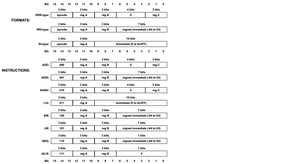
Hi,
I need to write behavioral VHDL code for RISC instruction set that
contains 8 instructions of each length is 16 bits.
there are 3 types of instructions for these 8 instructions
the 3 MSB of each instruction is for operation code.
i am using xilinx ISE.
an image is attached for the instruction set.

i need your help
Attached files:
-

my_vhdl.jpg
96 KB
Maxim M. wrote:
> i need your help
Usually its not the forum job to do others homework.

So lets try it this way: YOU start with something, then YOU show what
you have and tell us what problems you encounter with it. Then WE will
try to solve the problems together with YOU.

It seems to be a small register based CPU with 8 registers. Do you have
the "wrapper" for that ALU (="instruction set")? Or do you have to
implement the whole CPU core?

All in all its a fairly easy job. Good to start with VHDL and
simulation...
:
Edited by Moderator
really i am starting the coding, but i have an confusing in defining
signals.
i am assuming that i have 8 signals for registers, but what is the
length for each register? because for example instruction ADDI each
source register and destination register is 3 bits and the immediate
value is 7 bits?
so any starting point?
Maxim M. wrote:
> each source register and destination register is 3 bits
Those 3 bits are pointers to registers. Indeed you have 8 registers, and
the 3 bits are the address 0..7 to one of those 8 registers. I assume it
is a 8 bit CPU, so you have 8 registers with each 8 bit width.

A little hint: you don't have problems with VHDL at first. A HDL is a
hardware DESCRIPTION language. And to DESCRIBE something you must have a
picture of it. At least in mind, better on paper.
:
Edited by Moderator
Hi,

looks like RiSC-16 homework to me.
About the register length: You could try to guess from the name, or have
a look at the instruction set and find out what register bit width you
actually need to fully implement the instruction set. Hint: Look at LUI
and ADDI.
But I guess you should focus on the architecture and split problems into
different parts (fetch, decode, exec units). This should have been
explained in the lectures..

Cheers,

- Strubi
hello
here is sample of my code, is this write? any help?
1 | library IEEE; |
2 | use IEEE.STD_LOGIC_1164.ALL; |
3 | use IEEE.numeric_std.all; |
4 | use ieee.std_logic_arith.all; |
5 | use ieee.std_logic_unsigned.all; |
6 | |
7 | |
8 | -- Uncomment the following library declaration if using
|
9 | -- arithmetic functions with Signed or Unsigned values
|
10 | --use IEEE.NUMERIC_STD.ALL;
|
11 | |
12 | -- Uncomment the following library declaration if instantiating
|
13 | -- any Xilinx primitives in this code.
|
14 | --library UNISIM;
|
15 | --use UNISIM.VComponents.all;
|
16 | |
17 | entity alu is |
18 | generic ( |
19 | MAXWIDTH : integer := 16; |
20 | MAXDEPTH : integer := 12 |
21 | );
|
22 | end alu; |
23 | |
24 | architecture Behavioral of alu is |
25 | |
26 | -- CONSTANTS DECLARATION
|
27 | constant ADD : std_logic_vector(2 downto 0) := "000"; |
28 | constant ADDI : std_logic_vector(2 downto 0) := "001"; |
29 | constant NND : std_logic_vector(2 downto 0) := "010"; |
30 | constant LUI : std_logic_vector(2 downto 0) := "011"; |
31 | constant SW : std_logic_vector(2 downto 0) := "100"; |
32 | constant LW : std_logic_vector(2 downto 0) := "101"; |
33 | constant BEQ : std_logic_vector(2 downto 0) := "110"; |
34 | constant JALR : std_logic_vector(2 downto 0) := "111"; |
35 | |
36 | -- SIGNALS DECLARATION
|
37 | signal opcode : std_logic_vector(MAXWIDTH-1 downto MAXWIDTH-3); |
38 | signal regA : std_logic_vector(MAXWIDTH-4 downto MAXWIDTH-6); |
39 | signal regB : std_logic_vector(MAXWIDTH-7 downto MAXWIDTH-5); |
40 | signal regC : std_logic_vector(MAXWIDTH-14 downto 0); |
41 | signal imm7: std_logic_vector(MAXWIDTH-10 downto 0); |
42 | signal imm10: std_logic_vector(MAXWIDTH-7 downto 0); |
43 | |
44 | signal pc_reg : std_logic_vector(MAXWIDTH-1 downto 0); |
45 | signal pc_next : std_logic_vector(MAXWIDTH-1 downto 0); |
46 | signal ir_reg : std_logic_vector(MAXWIDTH-1 downto 0); |
47 | signal ir_next : std_logic_vector(MAXWIDTH-1 downto 0); |
48 | signal acc_reg : std_logic_vector(MAXWIDTH-1 downto 0); |
49 | signal acc_next : std_logic_vector(MAXWIDTH-1 downto 0); |
50 | begin
|
51 | process
|
52 | (
|
53 | pc_reg, pc_next, |
54 | ir_reg, ir_next, |
55 | acc_reg, acc_next |
56 | )
|
57 | variable opcode_v : std_logic_vector(2 downto 0); |
58 | begin
|
59 | opcode <= ir_reg(MAXWIDTH-1 downto MAXWIDTH-3); |
60 | regA <= ir_reg(MAXWIDTH-4 downto MAXWIDTH-6); |
61 | regB <= ir_reg(MAXWIDTH-7 downto MAXWIDTH-5); |
62 | regC <= ir_reg(MAXWIDTH-14 downto 0); |
63 | imm7 <= ir_reg(MAXWIDTH-10 downto 0); |
64 | imm10 <= ir_reg(MAXWIDTH-7 downto 0); |
65 | |
66 | opcode_v := opcode; |
67 | case (opcode_v) is |
68 | when ADD => |
69 | regA <= regB + regC; |
70 | |
71 | |
72 | |
73 | when NND => |
74 | regA <= regB nand regC; |
75 | |
76 | when others => |
77 | pc_next <= pc_reg; |
78 | end case; |
79 | end process; |
80 | |
81 | end Behavioral; |
Maxim M. wrote:
> use IEEE.numeric_std.all;
> use ieee.std_logic_arith.all;
> use ieee.std_logic_unsigned.all;
Either the first one OR the both last ones. But never ever all of them
together.
Otherwise you will encounter some funny and extremely strange error
messages about multiple definitions of operators and data types...

> variable opcode_v : std_logic_vector(2 downto 0);
Why a variable? You will not need a variable here, and so my my tip
is: do not use them. You could easily write a
1 | case (opcode) is ... |
instead.

> any help?
The first step is done. Now you must add some kind of flesh to that
bones.

1. At first: your ALU is very autistic. It has no input and no output.
The input will be the instruction word. Then you will have to create a
package that holds the register set for the 8x 16 bit registers. That
register set is an output, so it can be read from a upper/top level
module, but it can only be manipulated by the ALU itself.

2. I can not see any use for the *_next signals at all. The ALU itself
is completely combinatorial, so the only clock necessary is that one to
store the calculation results in the register set.

3. Why tricking around with generics? Your instruction format is
strictly defined. It is 16 bits wide and will not change. So there is
no use in defining a generic for a 18 bit or a 24 or a 13 bit format.

4. Set up a testbench for this neat project. Generate some stimuli
vectors to test the functionality...
Hi,

adding some mustard, as we say..

So you decided to start with the decode unit. Maybe forget about the ALU
at first, this would rather belong to the 'execute' stage.
As I mentioned before, you might want to sort out the general concept of
pipelining first. This typically results in the stages FETCH, DECODE,
EXECUTE, to obtain some speed. You can turn these stages into states,
then you just need to switch these each clock cycle. However, I think
that the latter is not the goal of this homework...
What you're doing right now is the "one cycle" approach, which often
results in a design with very poor performance when going for synthesis.
When only used in simulation, your code turns out hard to read for
others, when you pack all in one process.

So, a few more hints/pseudo questions, before my trap shuts:
- What stage would "        pc_next <= pc_reg;" belong to?
- What happens to the PC on a JUMP?
- Make a concept of the register file (this is small enough to fit in
distributed RAM, so you can read with one cycle latency)
- Are you aware of the hazards that can occur ? (these you'd typically
tackle last when regression testing with program code)

For the rest I can only second Lothar's comment: Simulate. You have to
write the test bench while writing your first code (which currently is
not functional at all, so there's no point in posting it). This is
painful to do in VHDL and there are better ways, but for homework,
you'll have to go through this to learn something :-)

Cheers,

- Strubi

P.S. If you're a purist, don't ever use ieee.std_logic_arith.all. It's
BROKEN by design.
really i dont know how to start coding in write way.
could you help me?
Please log in before posting. Registration is free and takes only a minute.
Existing account
Do you have a Google/GoogleMail account? No registration required!
Log in with Google account
Log in with Google account
No account? Register here.