Hello! So I am trying to display an image (maybe a square is a good
start) on two 8x8 bi-colored led matrices and then moving them
around(left, right, up, down) using the 4 buttons on the FPGA. I am
trying to make something like the good old Snake game that we all love!
:)
But as I am a beginner in VHDL I have no idea how to make this if
someone can give me some tips or a guide that would be useful for me to
follow that would be great! BTW its a University project if that
matters. :D
It sounds like having a problem with system design first, doesn't it?

We can't know how much knowldege you have yet. So, assuming, that you
are familiar with digital design and its basic elements (combinatorial
logic, Registers, RAMs etc.), which would be a reasonable basis for such
a project, I would recomand the following.

Step back und try to imagine the overall system. Watch your step, as
there could be a stool standing around :-)

You allready identified necessity of controlling LEDs. Matrix is a good
idea. Don't know, how? Try to find some circuits to do that focusing on
the matrix itself and switching by transistors. Those circuits are
usually meant to be used by a microcontroller. But their output is
comparable to that of an FPGA in respect being "digital". Only issue
could be that the output levels differ more or less slightly. But this
could be considered easily.

OK. Second. Some system to hold the image at its current state. State is
changing over time (as the snake is moving). Any idea?

Third: Some system, especially a system of representation of simple
graphical elements. This must be considered in conjunction with a fourth
system, which takes that description, interprets it and transfers bit
states at certain positions in the "thing" which holds the image.

Fourth: As said, a part, which interprets descriptions.

Fifth: A system which is able to manipulate the descriptions, defined by
point 3, implemented as point 4. regarding your objective it must be
able to manipulate x and y coordinates (in case your definition of such
a description uses them - I would use such coordinates. It must have an
input, whith the meaning of a direction which is then interpreted and
changes the parameters of the graphical objects.

Sixth: a system which takes input from the real word - a joystick, a
keyboard, just four push-swithces or something similar. This must read
in (possibly debounced) and converted to a form of data which may be
input to part 5.


Try to imagine this parts. First, in respect to their behavior more than
in that of their structure. But later, of course, more reallistic as you
must finally input some structure description in VHDL.

I would expect a series of sketches, which increase in detailedness.
First, some connections with a note, which information they transport. A
bunch of white boxes with some notes in it, what they do. Consider
system in and output of the whole system.

Possibly, this gives you an idea how to begin and to proceed to a point
where one may reason about.

Whish you good luck and always a pile of packages with coffee in your
kitchen. You will need it. :-)
Sorry. Being worried stirring in that pot of numbers. :-)

> ... converted to a form of data which may be input to part 5.
(I didn't mention any part #5).

must be

... converted to a form of data which may be input to part 4.
Damn! Must be part #5. I am so sorry. :-[

By the way. The system decomposition was only a proposal, Feel free to
divide parts in another way. But!

But its a good old engineers method to divide apparently "complex"
systems into parts. Reduce complexity. It's a good occasion to exercise
that.
Fourth point was a bit laconic.

What I meant was: Think about a way to "describe" the graphical elements
your matrix shall show. The result is just a paper, saying something
like:

My device will handle points of one dot. A dot is described by its x and
y coordinate on the matrix. Advance to other elements. Which information
will allow the distinction of dot and f.e. lines?

Each graphical element you want to display must be contained in that
description. And consider that each information and each set of
information which you use in your description must finally be physically
represented inside your FPGA as a certain bit pattern. You description
must describe that pattern, too.

OK. Hope that helps.
Attached files:
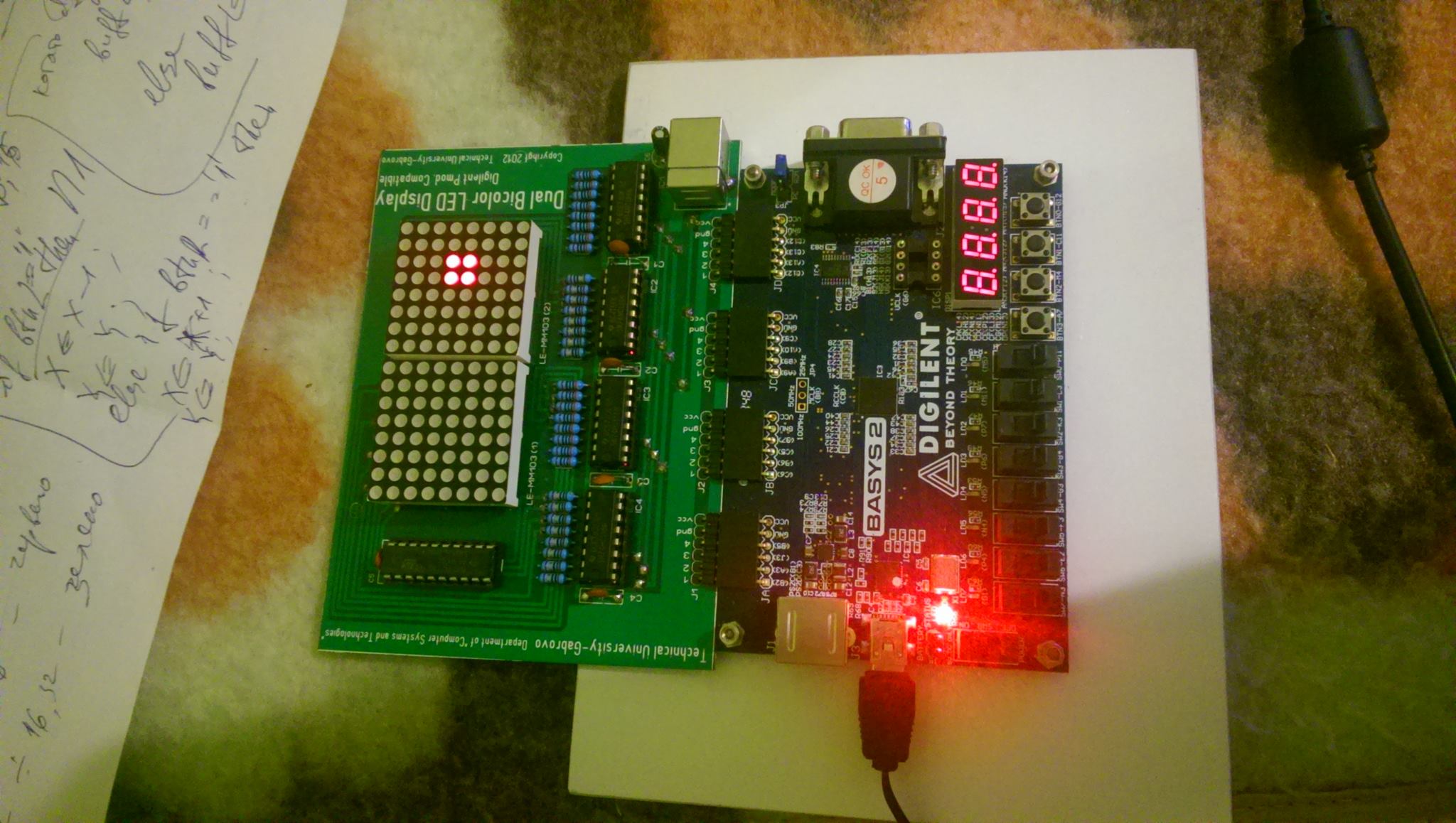
Thanks for the fast reply! So I managed to get the cube working also
getting it to move left and right but I still cant figure out how to
increment the buff using the y signal so I can move it up and down using
buttons 2 and 3...

Here is the code that I have done so far:
1 | library IEEE; |
2 | use IEEE.STD_LOGIC_1164.ALL; |
3 | use IEEE.STD_LOGIC_ARITH.ALL; |
4 | use IEEE.STD_LOGIC_UNSIGNED.ALL; |
5 | |
6 | |
7 | entity MatriciT is |
8 | Port ( clk : in STD_LOGIC; |
9 | rst : in STD_LOGIC; |
10 | decA0_4 : out STD_LOGIC_VECTOR(4 downto 0); |
11 | decA3_inv : out STD_LOGIC; |
12 | buff : out STD_LOGIC_VECTOR(7 downto 0); |
13 | btn_0 : in STD_LOGIC; |
14 | btn_1 : in STD_LOGIC; |
15 | btn_2 : in STD_LOGIC; |
16 | btn_3 : in STD_LOGIC); |
17 | end MatriciT; |
18 | |
19 | architecture Behavioral of MatriciT is |
20 | |
21 | signal x: STD_LOGIC_VECTOR(3 downto 0):="0111"; |
22 | signal y: STD_LOGIC_VECTOR(2 downto 0):="001";--x"3" |
23 | signal div: STD_LOGIC_VECTOR(31 downto 0); |
24 | |
25 | begin
|
26 | |
27 | process(clk,rst) is |
28 | begin
|
29 | if(rst = '1') then |
30 | div <=(others=> '0'); |
31 | elsif(clk='1' and clk'event) then |
32 | div<= div + 1; |
33 | end if; |
34 | end process; |
35 | |
36 | decA0_4(3 downto 0)<=div(18 downto 15); |
37 | decA0_4(4)<= '0'; |
38 | decA3_inv<= not div(18); |
39 | |
40 | |
41 | WIP : process (div(18 downto 15)) |
42 | begin
|
43 | if div(18 downto 15)=x |
44 | or div(18 downto 15)=x+1 |
45 | then buff<= "00011000"; |
46 | else
|
47 | buff<="00000000"; |
48 | end if; |
49 | end process; |
50 | |
51 | BTN : process (btn_0,btn_1,btn_2,btn_3) |
52 | begin
|
53 | if btn_0 = '1' |
54 | then x<=x+1; |
55 | end if; |
56 | if btn_1 = '1' |
57 | then x<=x-1; |
58 | end if; |
59 | if btn_2 = '1' |
60 | then y<=y+1; |
61 | end if; |
62 | if btn_3 = '1' |
63 | then y<=y-1; |
64 | end if; |
65 | |
66 | |
67 | end process; |
68 | end Behavioral; |
Seems, we each own a blanket, with the same design. :-)

-----

Seriously: Whow, whow, whow, whow. 19 hours to get form "How to do it at
all" to such a code. That's quite fast. Had any sleep? Or did you have
already started days before posing the first question?


Unfortunately you made some mistakes in regard to how to present the
problem and the code.

1. Use indenting. It will ease reading and understanding. You partially
did, but not enough.

2. Use "speaking" signal names. While the meaning of 'x' and 'y' is
likely to be derived from your question, something like 'decA0_4' is as
cryptic as one may wish. What the heck, does that mean? Same for 'div'
and 'buf'. We are able to make reasonable guesses but it is more kindly
to save us from guessing.

3. Use comments and verbal descritions. This is especially true in a
situation where you started from "How to at all"? We can't imagine in
which way you came to that code and can't hence come to any reasonable
opinion about how to proceed. At last, we are courious about your
project, too.

4. But at first: Clearly state your problem. Something, "it doesn't do"
isn't sufficient to help you. How should it work, and what's the result
of your attempt? What is 'buf' and why the heck shall it be manipulated
and in which way?

Understand me right: If it would be obvious, that you are an advanced
amateuer, we coud ommit explanations in detail as your code would speak
for itself and your question, while your question would touch the
essence of the problem. But in this case, neither is true.


It could not be overemphasized to work structured, perform analysis and
provide and exercise verbalisations. As this seems not the case with
professionals, they do it nonetheless - but inside their heads with much
lesser paperwork as at their beginnings.
Moi Fener wrote:1 | BTN : process (btn_0,btn_1,btn_2,btn_3) |
2 | begin
|
3 | if btn_0 = '1' |
4 | then x<=x+1; |
5 | end if; |
6 | if btn_1 = '1' |
7 | then x<=x-1; |
8 | end if; |
9 | :
|
10 | :
|
11 | end process; |
This code here (and also the cut code for y) forms a (gated)
combinational loop, because you have a counter WITHOUT a clock.

Funny thing: the simulation will look (almost) fine (little bit obscure
behaviour, when one button is hold and additionally another button is
pressed), but what would happen here in reality?

It looks like x would count up or down at maximum possible speed
(roughly 500MHz on a S3) when one of the buttons is pressed, but in fact
x is not more than a noise generator, because the carry isn't forwarded
fast enpough for reliable counting...

BTW: use identation to format your code in a readable manner...
:
Edited by Moderator
Please log in before posting. Registration is free and takes only a minute.
Existing account
Do you have a Google/GoogleMail account? No registration required!
Log in with Google account
Log in with Google account
No account? Register here.