EmbDev.net

Forum: FPGA, VHDL & Verilog SPI works sometimes


von Joshua V. (Company: Harvey Mudd College) (poofjunior)


Rate this post
useful
not useful
Hi everyone,

I'm writing SPI-addressable memory that is synchronous to the SPI sck 
clock signal.

So far, some components work as expected, but then cease working 
depending on how I add to it.

Currently, I receive data over SPI with a shift register. I send data 
over SPI with a shift register with asynchronous loading so that I can 
preset the data to send.

The issue is in generating the signal to preset the data to send.

I'd like to preset the shift register with a new byte every time 8 bits 
have passed along the spi bus while the CS line is pulled low. (aka, a 
multi-byte transfer)

Here's the issue: the code below does just that with the "sendNewData" 
signal. The problem is that it's very "sensitive to being changed."
1
module dataCtrl(input logic cs, sck, 
2
                output logic setNewData);
3
4
    logic [3:0] bitCount;
5
   
6
    assign andOut = bitCount[2] & bitCount[1] & bitCount[0];
7
8
      
9
      always_ff @ (negedge sck, posedge cs)
10
    begin
11
        if (cs)
12
    begin
13
            bitCount <= 3'b0000;
14
        setNewData <= 1'b1;
15
        end
16
        else
17
        begin
18
    bitCount <= bitCount + 3'b0001;
19
    setNewData <= andOut;
20
        end
21
    end
22
endmodule


If I extend the width of the bitCount signal to 5 or more bits wide, 
aka: change from
1
    logic [3:0] bitCount;
to
1
    logic [4:0] bitCount;
the code doesn't generate the signal at the right time, and I get data 
transferred that is off by one. Does this make sense? I'd like to build 
up this module to output other control signals, but I'm hinging my 
design on being able to count past 8. Strangely enough, extending this 
module in pretty-much any way that builds off of the existing components 
reproduces this problem. Do adders need more than one clock cycle to add 
if their signals are larger than 4 bits?

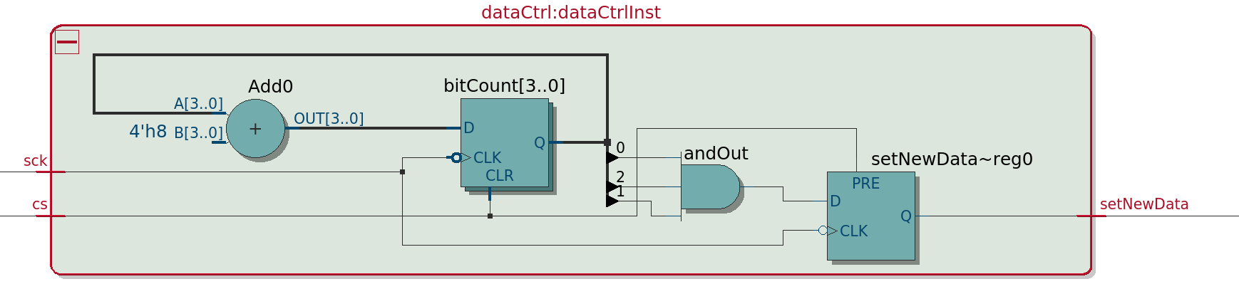
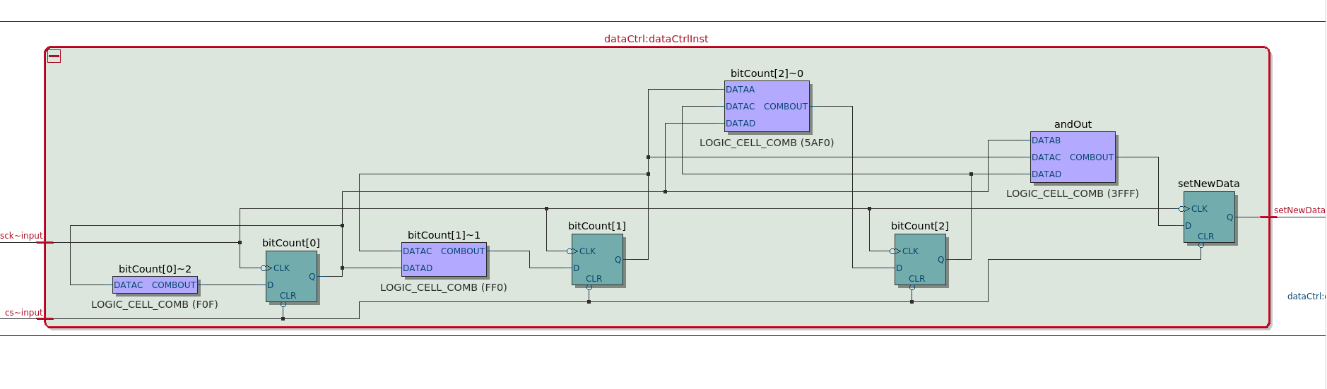
I've attached 3 files. The high-level working module. A detailed view of 
that same module with the hardware used, and the detailed view of the 
module with the larger bitCount signal that doesn't work. (Lastly, the 
compiler optimizes away bitCount[3], which isn't used, although the 
logic is different.)

Thanks a bunch for your thoughts and input!

Lastly: I'm using a ...
Altera Cyclone IV from a De0 Nano
Quartus II 13.1 Web Edition

von Lothar M. (Company: Titel) (lkmiller) (Moderator)


Rate this post
useful
not useful
Joshua Vasquez wrote:
> the code doesn't generate the signal at the right time, and I get data
> transferred that is off by one.
How do you see that? What does the simulation say?

> The problem is that it's very "sensitive to being changed."
Sounds like a "tsu-th-problem" and a race condition.

> Do adders need more than one clock cycle to add if their signals are
> larger than 4 bits?
Look at it the other way: a counter with less than 5 bits is able to get 
the result just in time to read the correct word. As far as I see it, 
the "setNewData" must be one to late!
But over all: the problem is an interaction with the rest of the code, 
because the code you presented is completely synchronous to sck and will 
not have a problem on its own.

Joshua Vasquez wrote:
> Do adders need more than one clock cycle to add if their signals are
> larger than 4 bits?
No. An adder is one of the fastest thing in a FPGA, its absolutely 
optimized, because each counter is based on an adder and counter are 
heavyly used in FPGAs.
And of course: an adder never can be to slow for a clock. Only a clock 
can be too fast for an adder! But you don't have to think about such 
things at clock frequencies below 100MHz...

von Joshua V. (Company: Harvey Mudd College) (poofjunior)


Attached files:

Rate this post
useful
not useful
Thanks for the reply!

I started off by running it on the FPGA directly and sending SPI 
messages across via an Arduino. When the bitCount register is 4 bits 
wide, the test value sent from the FPGA (8'b00000111) is received as 7 
on the Arduino. When bitCount is 5 or more bits wide, the Arduino 
receives 3 instead. No other changes are applied to get this output.

My waveform looks all right(from a design where bitCount is 5 bits wide, 
though that version doesn't work on the FPGA.)
The setNewData signal triggers the preset value to capture the data to 
send through the shift registers on the next clock cycle. My assumption 
is that data gets loaded into the shift registers on the rising edge of 
this signal.

I've added a picture of the spi shift registers to show how the data 
gets loaded.

von Lothar M. (Company: Titel) (lkmiller) (Moderator)


Rate this post
useful
not useful
Joshua Vasquez wrote:
> spiShiftRegisters.png
If ALOAD means "asynchronous load" then you can find a race condition in 
this module: when the sclk shift out the last data bit with the very 
same edge the signal setNewData becomes active and loads the shift 
register. so you will have a glitch on the output. Although it may not 
be the actual problem, it is not nice.

> is received ... on the Arduino.
I would dig deeper here: maybe there the wrong SPI mode. And a minor 
change to the timing on the MISO output of the FPGA leads to a different 
value.

von Joshua V. (Company: Harvey Mudd College) (poofjunior)


Rate this post
useful
not useful
Lothar Miller wrote:
> If ALOAD means "asynchronous load" then you can find a race condition in
> this module: when the sclk shift out the last data bit with the very
> same edge the signal setNewData becomes active and loads the shift
> register. so you will have a glitch on the output. Although it may not
> be the actual problem, it is not nice.

Thanks; right now I'm conforming to SPI-mode-0, which I'm taking as: 
data gets captured by both devices (master and slave) on the rising edge 
of SCK and changes on the falling edge of SCK. As long as they both 
agree to this standard, neither will try to sample the other while the 
other is changing.

One place that I could definitely be going wrong is my understanding of 
ALOAD. I'm thinking of it as an edge-triggered, so that data gets 
captured onto the shift register only on positive "setNewData" signal 
edges. If ALOAD is actually a latch and is transparent whenever the 
"setNewData" signal is high, then that could mean that changing data 
when the latch becomes opaque could be my problem.

von Lothar M. (Company: Titel) (lkmiller) (Moderator)


Rate this post
useful
not useful
Joshua Vasquez wrote:
> LOAD. I'm thinking of it as an edge-triggered,
For sure it isn't, because otherwise you would have a 
double-clock-flipflop with two separate data inputs. And such a thing 
doesn't exist...

von Joshua V. (Company: Harvey Mudd College) (poofjunior)


Attached files:

Rate this post
useful
not useful
Lothar Miller wrote:
> If ALOAD means "asynchronous load" then you can find a race condition in
> this module: when the sclk shift out the last data bit with the very
> same edge the signal setNewData becomes active and loads the shift
> register. so you will have a glitch on the output. Although it may not
> be the actual problem, it is not nice.

This lead me down the right path! I was letting my data change as the 
shift register was clocking in new data. It turns out that I wasn't 
paying close attention to when data is supposed to be captured onto the 
shift register. Rather than stop capturing data at the falling edge of 
the first sck pulse, I should stop capturing data on the rising edge of 
the first sck pulse, that way the signal isn't being shifted out as it 
is being captured.

I posted the revised waveform with the correct setNewData signal. It's 
also working on the FPGA now too :)

(Lastly, by "captured," I mean release the aload signal and let the 
input data signal go opaque to its input)

Finally, thanks for clearing up that haziness about the asynchronous 
loading. It makes sense that it shouldn't be edge triggered...

Please log in before posting. Registration is free and takes only a minute.
Existing account
Do you have a Google/GoogleMail account? No registration required!
Log in with Google account
No account? Register here.