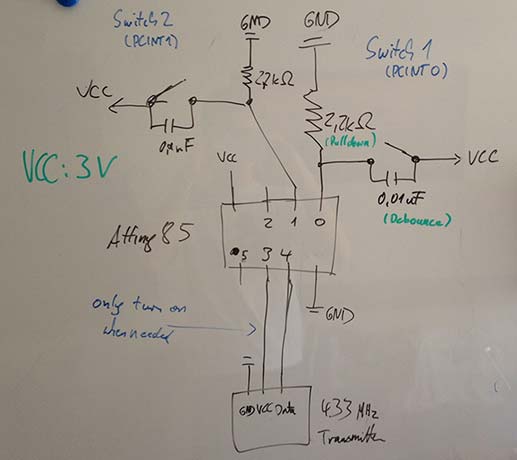
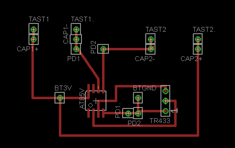
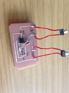
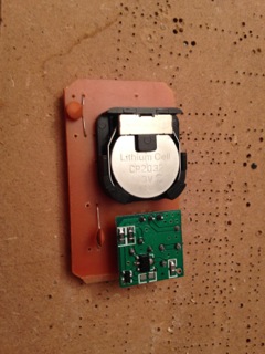
Hi,

I'm currently building a 433MHz remote with two buttons. The remote is
controlled by an Attiny85v(8MHz). Sadly it does not work very reliable,
sometimes it works other times nothing happens.

Here some explanations on what I did and why:

Each of the buttons triggers a pin change interrupt which wakes the
Attiny from sleep. After that I check which button was pressed and turn
on or off the lights via 433MHz switches. But those buttons don't work
very reliable. Sometimes they do what they should other times I need to
press them for several seconds before something happens, sometimes
nothing happens at all. I don't know why, either I have a bug in my code
or in the circuit for the buttons.

I use a 2.2k resistor to pull the button pins (0 and 1) to GND. When
pressing the button, the pins will be pulled HIGH. To avoid "bouncing"
of the tactile switch I added an 0.01uf capacitor in parallel.

I tried to keep the code simple and added comments.I am currently
building a 433MHz remote with two buttons. The remote is controlled by
an Attiny85v(8MHz). Sadly it does not work very reliable, sometimes it
works other times nothing happens.

Here some explanations on what I did and why:

Each of the buttons triggers a pin change interrupt which wakes the
Attiny from sleep. After that I check which button was pressed and turn
on or off the lights via 433MHz switches. But those buttons don't work
very reliable. Sometimes the do what they should other times I need to
press them for several seconds before something happens. I don't know
why, either I have a bug in my code or in the circuit for the buttons.

I use a 2.2k resistor to pull the button pins (0 and 1) to GND. When
pressing the button, the pins will be pulled HIGH. To avoid "bouncing"
of the tactile switch I added an 0.01uf capacitor in parallel.

I attached the commented code and images of my circuit as well as the
final board.
Attached files:
-

Schaltplan.jpg
20 KB -

BoardEagle.png
9.4 KB -

Front.jpg
28 KB -

Rueckseite.jpg
32 KB
Sorry for the double text and missing code, I can't edit the post
anymore.

I attached the code, you can also find it here:
http://pastebin.com/hzw0j3FW
Please log in before posting. Registration is free and takes only a minute.
Existing account
Do you have a Google/GoogleMail account? No registration required!
Log in with Google account
Log in with Google account
No account? Register here.