Hi everyone!

I'm writing a vhdl code for the system in attachment. I have no error
when I compile the code but I have an error when I elaborate.

ncelab: *E,CSGMSS: multiple sources for unresolved signal: INT1
[4.3.1.2].
           Computing driving value:
:systeme_comparateur_tb(archi):uut@systeme_c
omparateur(archi):int1
In port map at: ../sources/systeme_comparateur_arch.vhdl, line: 95,
position: 34

This is my code below:
1
libraryieee;
2
useieee.std_logic_1164.all;
3
4
libraryanalogdevice_lib;
5
useanalogdevice_lib.all;
6
7
libraryst_lib;
8
usest_lib.all;
9
10
entitysysteme_comparateuris
11
12
port(enable_mux4_comp1,
13
enable_mux8_comp1,
14
enable_mux4_comp2,
15
enable_mux8_comp2:instd_logic;
16
A_mux4_comp1,
17
A_mux4_comp2:instd_logic_vector(1downto0);
18
A_mux8_comp1,
19
A_mux8_comp2:instd_logic_vector(2downto0);
20
S_mux4_comp1,
21
S_mux4_comp2:inreal_vector(3downto0);
22
S_mux8_comp1,
23
S_mux8_comp2:inreal_vector(7downto0);
24
In_switch:instd_logic;
25
Sortie_comp1,
26
Sortie_comp2:outreal);
27
28
endsysteme_comparateur;
29
30
31
architecturearchiofsysteme_comparateuris
32
33
componentanalog_ADG704
34
35
generic(INPUTS_SEL:integer);
36
37
port(EN:instd_logic;
38
A:instd_logic_vector(INPUTS_SEL-1downto0);
39
S:inreal_vector(2**INPUTS_SEL-1downto0);
40
D:outreal);
41
42
endcomponent;
43
44
componentanalog_ADG708
45
46
generic(INPUTS_SEL:integer);
47
48
port(EN:instd_logic;
49
A:instd_logic_vector(INPUTS_SEL-1downto0);
50
S:inreal_vector(2**INPUTS_SEL-1downto0);
51
D:outreal);
52
53
endcomponent;
54
55
componentanalog_comparateur
56
57
generic(vcc:real;
58
gnd:real);
59
60
port(in_pos:inreal;
61
in_neg:inreal;
62
s_comp:outreal);
63
64
endcomponent;
65
66
componentanalog_ADG712_1
67
68
port(In_ADG_1:instd_logic;
69
D_ADG_1:inreal;
70
S_ADG_1:outreal);
71
72
endcomponent;
73
74
signalint1,int2,int3,int4:real;
75
76
begin
77
78
mux4_comp1:analog_ADG704
79
80
genericmap(INPUTS_SEL=>2)
81
82
portmap(enable_mux4_comp1,
83
A_mux4_comp1,
84
S_mux4_comp1,
85
int1);
86
87
mux8_comp1:analog_ADG708
88
89
genericmap(INPUTS_SEL=>3)
90
91
portmap(enable_mux8_comp1,
92
A_mux8_comp1,
93
S_mux8_comp1,
94
int2);
95
96
comp1:analog_comparateur
97
98
genericmap(vcc=>5.0,gnd=>0.0)
99
100
portmap(int1,int2,Sortie_comp1);
101
102
mux4_comp2:analog_ADG704
103
104
genericmap(INPUTS_SEL=>2)
105
106
portmap(enable_mux4_comp2,
107
A_mux4_comp2,
108
S_mux4_comp2,
109
int3);
110
111
mux8_comp2:analog_ADG708
112
113
genericmap(INPUTS_SEL=>3)
114
115
portmap(enable_mux8_comp2,
116
A_mux8_comp2,
117
S_mux8_comp2,
118
int4);
119
120
comp2:analog_comparateur
121
122
genericmap(vcc=>5.0,gnd=>0.0)
123
124
portmap(int3,int4,Sortie_comp2);
125
126
switch:analog_ADG712_1
127
128
portmap(In_switch,int3,int1);
129
130
endarchi;
With this code, I can't run a simulation. So I think I'm wrong when I
connect the ports of ADG712 component with the rest of the system.

Could you help me please ?
mux4_comp1: analog_ADG704
generic map (INPUTS_SEL => 2)
port map (enable_mux4_comp1,
A_mux4_comp1,
S_mux4_comp1,
int1);
....
switch: analog_ADG712_1
port map (In_switch, int3, int1);
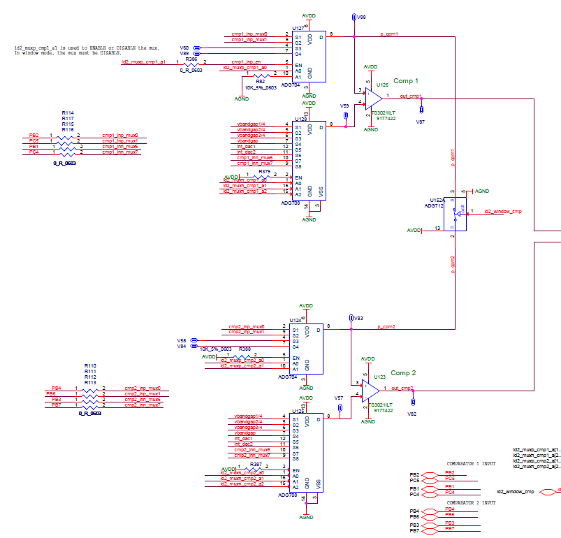
int1 is used as out signal from 2 components?
I use int1 signal to modelise the wire between ADG704 (U127) output and
TS3021ILT (U126) positive input. So, if you get a look on the schema,
there is the port '3' of ADG712 (U152A) which is also connected on this
wire. I don't know if it's correct...
I think, you have to create a new components, which takes two inputs
(both int1) and creates one resulting signal.
You have to specify the best way how to combine both signals(and, or ,
sum, select). It depends on your goals.
agathepower wrote:> component analog_ADG704> generic (INPUTS_SEL: integer);> port(EN : in std_logic;> A : in std_logic_vector (INPUTS_SEL-1 downto 0);> S : in real_vector (2**INPUTS_SEL-1 downto 0);> D : out real);>> component analog_ADG712_1> port(In_ADG_1: in std_logic;> D_ADG_1: in real;> S_ADG_1: out real);
The models of the switches are wrong. According to the datasheet, all of
the S are inout and also D is inout.
How do the models reflect the state "switch off"/"all switches off" to
the d output? Is there a 'Z' level possible on the output (as it will be
in reality)? How do you resolve the conflict when one switch drives 'Z'
and another switch drives "3.3" on the same wire?
All in all you cann say: the VHDL description is not equal to the
schematic, because in a switch both terminals are inout and a switch can
be high-Z (just "open").
All in all I would say that you will need a special type for the
"analog" signals. You need a type thats possible to reflect the high-Z
value of an open switch. So have a look at this switch model (google
translate will help out):
http://www.lothar-miller.de/s9y/archives/91-Schalter-und-Bruecke.html
Maybe it gives you a hint how to build such a switch.
Hi and thank you for your answer!
Lothar Miller wrote:> The models of the switches are wrong. According to the datasheet, all of> the S are inout and also D is inout.
I know, in fact the code in your link is working with std_logic but not
with real. I already tested that. With real the error "multiple sources
for unresolved signal" occurs in elaboration.
To pass through this issue I modelise only D to S, that why I have D:in
and S:out in my code, because according to my tutor in this system there
is only one possible sens.
If we imagine that not a ADG712 component but just a switch with an
input, an output, and a command signal, how can I connect these ports
with the rest of the system without error?
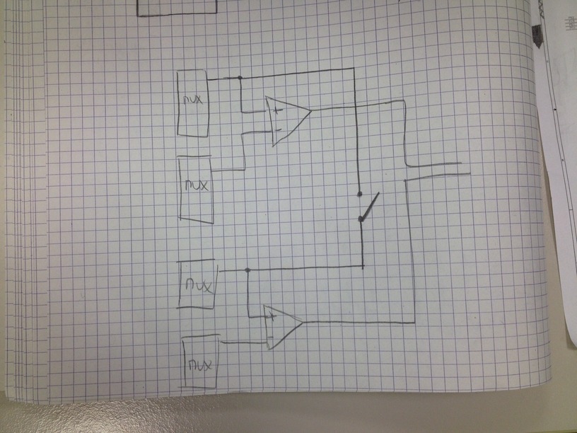
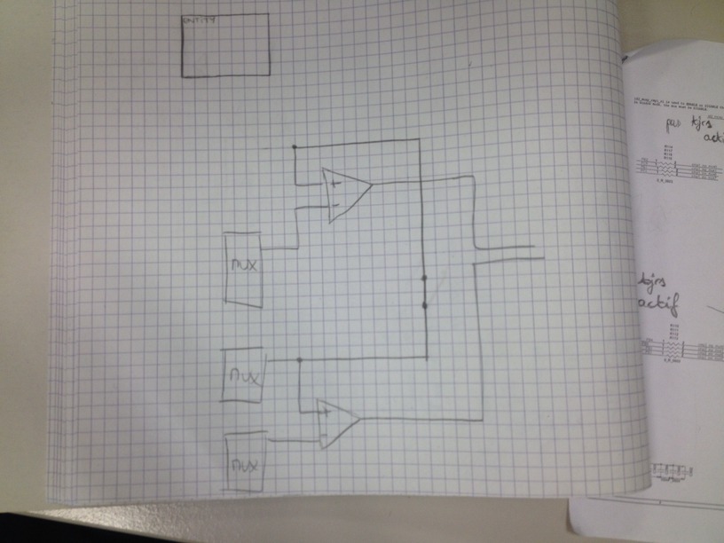
I put the schemas in attachment
agathepower wrote:> If we imagine that not a ADG712 component but just a switch with an> input, an output, and a command signal, how can I connect these ports> with the rest of the system without error?
You can't implement a switch for real numbers. Just try to tell me:
what would be on the output of this switch, if the input is 1.11 and the
switch is on?
And what would be the output when the switch is switched off?
Why isn't it possible to handle this second case with a real value?
The only possibility you have is to implement a 2:1 multiplexer. That
can be done with a real number. And the input of that mux is either the
output of the lower mux and the output of the upper opamp in your
sketches...
BTW: I scaled down your images size by a factor of 30 without any loss
of information.
Lothar Miller wrote:> The only possibility you have is to implement a 2:1 multiplexer
Thank you, I think that is the right solution.
Nothing to do with it, but I have an other question. Is it possible to
connect an internal signal to a "bit" of a vector (not a bit but I don't
know how to say it with "real") ?
In fact I want to connect signals generator on each S inputs of each
mux. I have already the signal generator, it's an entity with no input
and one output, this output is connected to an internal signal and this
signal is connected to a "bit" of S vector on each mux.
I don't know if I'm clear...
Thank you for your help