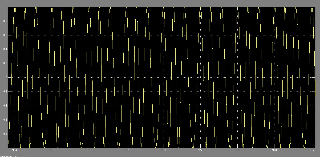
I need to create a Verilog or VHDL testbench to simulate the zero cross
detection of a modulated FM sinusoidal wave. I need to know how to
generate a frequency modulated signal(as showed in the attached file)
using Verilog or VHDL to simulate in modelsim. Please help me.
Attached files:
-

modulation.jpg
270 KB
It works that way: YOU show US something. And then we can discuss about
that and give you some hints. But no one here is intended to do your
homework.

So: how would you generate a sine curve in VHDL? And afterwords: how can
this sine be modulated? Lets say it this way: you can have easily it in
about 20-30 lines of vhdl code.. and thats the "long" version...

Look at this for an easy start:
Beitrag "Re: Sinus (real) für Testbench erzeugen"
Beitrag "Variable "now" einheit anpassen"
Beitrag "Zeit messen in Testbench"
Beitrag "Re: [VHDL] Daten von ADC in BRAM speichern"
:
Edited by Moderator
Please log in before posting. Registration is free and takes only a minute.
Existing account
Do you have a Google/GoogleMail account? No registration required!
Log in with Google account
Log in with Google account
No account? Register here.