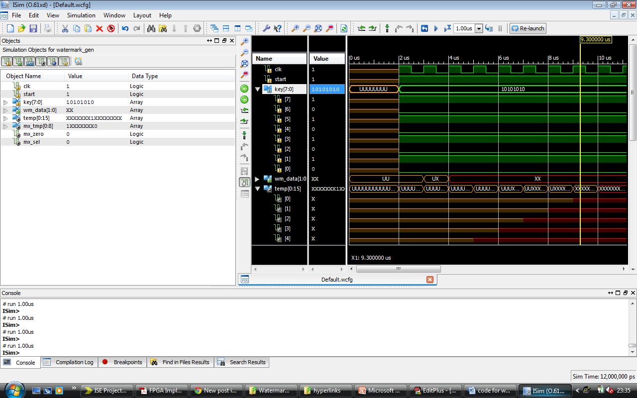
I am designing and LFSR based pseudo code generator.. but the final
output is coming as unknown.. can anybody help me to rectify this issue.
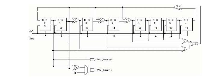
I have attached the circuit diagram, code & output wave form. In the
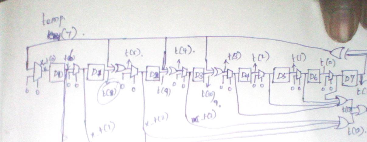
circuit before each FF i have added an Mux..
Code
========================
ENTITY watermark_gen IS
PORT(
clk : IN std_logic;
start : IN std_logic;
key : in std_logic_vector (7 downto 0);
wm_data : OUT std_logic_vector (1 DOWNTO 0)
);
-- Declarations
END ENTITY watermark_gen ;
--
ARCHITECTURE struct OF watermark_gen IS
component D_ff is
port( d,clock,enable : in std_logic;
q,qbar : out std_logic);
end component;
component nor1 is
port ( x,y : in std_logic;
z : out std_logic);
end component;
component or3 is
port (w,x,y : in std_logic;
z : out std_logic);
end component;
component or4 is
port ( v,w,x,y : in std_logic;
z : out std_logic);
end component;
component mux1 is
port ( x: in std_logic;
y: in std_logic;
c: in std_logic;
z: out std_logic);
end component;
component xor1 is
port (x,y : in std_logic;
z : out std_logic);
end component;
signal temp : std_logic_vector(0 to 15):= "0000000000000000";
signal mx_tmp: std_logic_vector(0 to 8):="000000000";
signal mx_zero: std_logic := '0';
signal mx_sel: std_logic := '0';
BEGIN
temp(7) <= key(7);
temp(6) <= key(6);
temp(5) <= key(5);
temp(4) <= key(4);
temp(3) <= key(3);
temp(2) <= key(2);
temp(1) <= key(1);
temp(0) <= key(0);
p1: mux1 port map ( temp(7),mx_zero,mx_sel,mx_tmp(0));
p2: D_ff port map ( mx_tmp(0),clk,start,temp(6),open);
p3: mux1 port map ( temp(6),mx_zero,mx_sel,mx_tmp(1));
p4: D_ff port map ( mx_tmp(1),clk,start,temp(8),open);
p5: xor1 port map ( temp(7),temp(8),temp(5));
p6: mux1 port map ( temp(5),mx_zero,mx_sel,mx_tmp(2));
p7: D_ff port map ( mx_tmp(2),clk,start,temp(9),open);
p8: xor1 port map ( temp(7),temp(9),temp(4));
p9: mux1 port map ( temp(4),mx_zero,mx_sel,mx_tmp(3));
p10: D_ff port map ( mx_tmp(3),clk,start,temp(10),open);
p11: xor1 port map ( temp(7),temp(10),temp(3));
p12: mux1 port map ( temp(3),mx_zero,mx_sel,mx_tmp(4));
p13: D_ff port map ( mx_tmp(4),clk,start,temp(2),open);
p14: mux1 port map ( temp(2),mx_zero,mx_sel,mx_tmp(5));
p15: D_ff port map ( mx_tmp(5),clk,start,temp(1),open);
p16: mux1 port map ( temp(1),mx_zero,mx_sel,mx_tmp(6));
p17: D_ff port map ( mx_tmp(6),clk,start,temp(0),open);
p18: mux1 port map ( temp(0),mx_zero,mx_sel,mx_tmp(7));
p19: D_ff port map ( mx_tmp(7),clk,start,temp(11),open);
p20: or3 port map ( mx_tmp(1),mx_tmp(2),mx_tmp(3),temp(12));
p21: or4 port map ( mx_tmp(4),mx_tmp(5),mx_tmp(6),mx_tmp(7),temp(13));
p22: nor1 port map ( temp(12),temp(13),temp(14));
p23: xor1 port map ( temp(11),temp(14),temp(15));
wm_data(0) <= mx_tmp(1);
wm_data(1) <= mx_tmp(1) xor mx_tmp(2);
END ARCHITECTURE struct;
Attached files:
-

Simulator_Output.jpg
160 KB -

Circuit.jpg
28 KB
why dont you use something like:

signal sr:std_logic_vector(7 downto 0);
begin
process
 begin
  wait until rising_edge(clk);

  sr <= sr(6 downto 0) & (sr(7) xnor sr(0));

end process;
Thanks for your suggestion.. but i need to implement the given circuit
in structural manner... i have almost implemented but some where i am
missing a simple logic.. i don't know where
Does that code really translate without problems?

Shouldn't e.g. the following lines

  temp(5) <= key(5);
  ...
  p5: xor1 port map ( temp(7),temp(8),temp(5));

result in the error 'net temp(5) has multiple driver(s)'? (and the same
applies to many other signals)
Yes... i need to pass the input the key values for the flip flop..at the
same time these flip flops might be inter - connected. i think the issue
is due to multiple drives for a signal.. is there a way to resolve it..
i have resolved this issue very long back but now i forgot it..i needed
to fix this immediately.
This kind of low level structural description is absolutely stupid! No
one can read this kind of code! And is is also difficult to write.

If I ever see this kind of code in my company, I'd get the author fired
immediately!
i think he does that for study, as an problem he has to solve as
homework. and it is not soooo stupid to do that, because it is a very
good way to understand how a lfsr works in hardware. just like if it was
build from discreed flipflop ICs on a breadboard.
> In the circuit before each FF i have added an Mux...
So, pls show a picture of your actual structure, not one, that "looks
fairly similar"...
Ya.. we do it for study purpose and we want to solve the issue.. i don't
think this is wrong. because these kind of stuffs will help us to learn
many things.. at we should know why we should not code like this.. so if
any one interested to solve this issue help me.. i am also trying from
my side
> i think the issue
> is due to multiple drives for a signal.. is there a way to resolve it..

well: if you need to define a temporal sequence then a D_FF might not be
the worst thing to use (it allows to distiguish the time before CLK-edge
and after CLK-edge)

If you want to set different values to a signal for initalization and
for the following normal operation, then you might need:
1) a mux, which assigns either the init value or the normal-operation
value to that signal.
2) a signal, which tells the mux which of both connections should
choosen. A synch reset input might often be the appropriate for that,
for your specific problem an internal signal initphase might even be
better: after the reset it should go active for exactly one CLK-cycle
(so that the intended initialization is done), and it should go inactive
for all following CLK-cycles (so that normal operation takes place).

You make use of all needed components in your code already, you only
need to arrange them properly.
oops, I didn't update before submitting, so I did not consider your last
post.

I think the circuit you've drawn is a step in the right direction, but
you have to make real use of the muxes (connect a relevant signal to the
y input and connect a relevant signal to the c input).
I don't see key in your drawing.

What should the key do?
Set am initial to the LFSR? If so you remove the zeros in front of the
muxes and replace them with the key.
I have passed the key value to the mux as input and another input for
the mux is the LFSR feed back with the D-FF connecting lines. also i
have passed the clock as input for the mux.. this is working but it
returning only two values in the output.. they are 00 and 10.
> also i have passed the clock as input for the mux.

???

Maybe you should reconsider, what a mux is made for. The hints, how you
should control your mux, were already given above.
Ya.. thanks.. i have used the mux to first place the key value before
the D-FF and then only the feed back signal is connected. So i just used
the mux to initialize the FFs with the key values then it will work as a
LFSR.. now i am getting the random sequence number i needed. thanks for
all your replies..
sudhakaran krishnasamy wrote:
> i just used the mux to initialize the FFs with the key values
This you can also achieve by using the propriate set/reset pins of the
(synchronous) D-flipflop inside the FPGA. See this here:
http://www1.pldworld.com/@xilinx/html/technote/TOOL/MANUAL/15i_doc/ALLIANCE/lib/lib5_28.htm
Then you will not need any mux to "load" the initial value. With your
"intermediate mux construct" you user more ressources than necessary...
Please log in before posting. Registration is free and takes only a minute.
Existing account
Do you have a Google/GoogleMail account? No registration required!
Log in with Google account
Log in with Google account
No account? Register here.