Hey guys
I have a presentation for next couple days on VHDL and i need to show
some simple example project, I managed to write a <b>4 Bit Adder</b> as
follow:
Adder4.vhd:
1 | library ieee;
|
2 | use ieee.std_logic_1164.all;
|
3 |
|
4 | ENTITY Adder4 IS
|
5 | PORT
|
6 | (
|
7 | Cin : IN STD_LOGIC;
|
8 | X, Y : IN STD_LOGIC_VECTOR (3 DOWNTO 0);
|
9 | R : OUT STD_LOGIC_VECTOR (3 DOWNTO 0);
|
10 | Cout : OUT STD_LOGIC
|
11 | );
|
12 | END Adder4;
|
13 |
|
14 | ARCHITECTURE Adder4_Behav OF Adder4 IS
|
15 | SIGNAL Carry : STD_LOGIC_VECTOR ( 2 DOWNTO 0);
|
16 |
|
17 | COMPONENT FullAdder
|
18 | PORT
|
19 | (
|
20 | Cin, A, B : IN STD_LOGIC;
|
21 | Cout, S : OUT STD_LOGIC
|
22 | );
|
23 | END COMPONENT;
|
24 | BEGIN
|
25 | FA0: FullAdder PORT MAP ( Cin, X(0), Y(0), Carry(0), R(0));
|
26 | FA1: FullAdder PORT MAP ( Carry(0), X(1), Y(1), Carry(1), R(1));
|
27 | FA3: FullAdder PORT MAP ( Carry(1),X(2),Y(2),Carry(2),R(2));
|
28 | FA4: FullAdder PORT MAP ( Carry(2),X(3),Y(3),Cout,R(3));
|
29 | END;
|
FullAdder.vhd
1 | library ieee;
|
2 | use ieee.std_logic_1164.all;
|
3 |
|
4 | ENTITY FullAdder IS
|
5 | PORT
|
6 | (
|
7 | Cin, A, B : IN STD_LOGIC;
|
8 | Cout, S : OUT STD_LOGIC
|
9 | );
|
10 | END FullAdder;
|
11 |
|
12 | ARCHITECTURE FullAdder_Behav OF FullAdder IS
|
13 | BEGIN
|
14 | S <= A XOR B XOR Cin;
|
15 | Cout <= (A AND Cin) OR (B AND Cin) OR (A AND B);
|
16 | END;
|
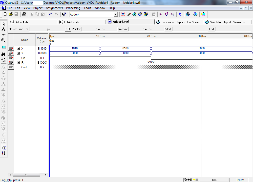
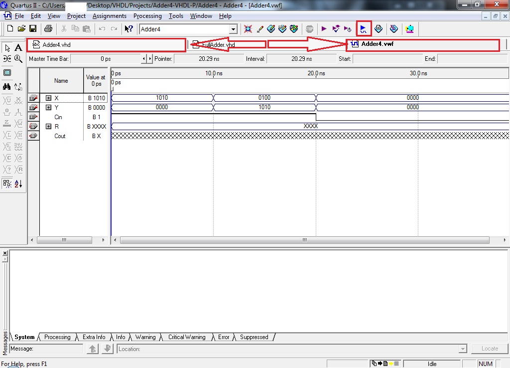
but when i run simulation the output result is not synced at all!
I know i am not considering something here, but what is that?
I need HELP ASAP, please :(
What is it that i am doing wrong!?

I have posted the *.vwf and the simulation result as attachments

Thanks in advace