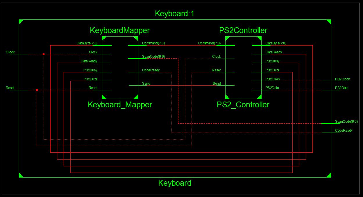
Hello everybody,

I have been learning VHDL for a month now and am stuck with this project
in which I am trying to connect a PS2 keyboard to my FPGA board and show
the letters typed on the 7segment display. I am near to end, however am
stuck in matching the scancode values with their corresponding 7bit
binary representations for SSD. I have added a Matcher module of course,
but I can not add that module to top module properly. Even if it is
shown under the topmodule, I can not see it in RTL schematic. I am
adding my Top module and Matcher Module and a SS of my schematic.

The weird thing is that, even though I do not have an output ScanCode in
my top module, RTL seems to do/behave so.
 I need your help!

Thanks!

Top Module:
1 | library IEEE; |
2 | use IEEE.STD_LOGIC_1164.ALL; |
3 | use IEEE.STD_LOGIC_ARITH.ALL; |
4 | use IEEE.STD_LOGIC_UNSIGNED.ALL; |
5 | |
6 | entity Keyboard is |
7 | port (Reset : in STD_LOGIC; |
8 | Clock : in STD_LOGIC; |
9 | PS2Clock : inout STD_LOGIC; |
10 | PS2Data : inout STD_LOGIC; |
11 | CodeReady : out STD_LOGIC; |
12 | --ScanCode : out STD_LOGIC_VECTOR(9 downto 0);
|
13 | SEGMENTS : out STD_LOGIC_VECTOR(6 downto 0)); |
14 | end Keyboard; |
15 | |
16 | architecture Behavioral of Keyboard is |
17 | |
18 | signal Send : STD_LOGIC; |
19 | signal Command : STD_LOGIC_VECTOR(7 downto 0); |
20 | signal PS2Busy : STD_LOGIC; |
21 | signal PS2Error : STD_LOGIC; |
22 | signal DataReady : STD_LOGIC; |
23 | signal DataByte : STD_LOGIC_VECTOR(7 downto 0); |
24 | signal ScanCode : STD_LOGIC_VECTOR(9 downto 0); |
25 | signal ScanCode2 : STD_LOGIC_VECTOR(7 downto 0); |
26 | begin
|
27 | |
28 | PS2_Controller: entity work.PS2Controller |
29 | port map (Reset => Reset, |
30 | Clock => Clock, |
31 | PS2Clock => PS2Clock, |
32 | PS2Data => PS2Data, |
33 | Send => Send, |
34 | Command => Command, |
35 | PS2Busy => PS2Busy, |
36 | PS2Error => PS2Error, |
37 | DataReady => DataReady, |
38 | DataByte => DataByte); |
39 | |
40 | Keyboard_Mapper: entity work.KeyboardMapper |
41 | port map (Clock => Clock, |
42 | Reset => Reset, |
43 | PS2Busy => PS2Busy, |
44 | PS2Error => PS2Error, |
45 | DataReady => DataReady, |
46 | DataByte => DataByte, |
47 | Send => Send, |
48 | Command => Command, |
49 | CodeReady => CodeReady, |
50 | ScanCode => ScanCode); |
51 | |
52 | ScanCode2 <= ScanCode (7 downto 0); |
53 | |
54 | Matcher: entity work.Matcher |
55 | port map ( SCANCODE => ScanCode2, |
56 | SEGMENTS => SEGMENTS); |
57 | |
58 | end Behavioral; |
Matcher Module:
1 | library IEEE; |
2 | use IEEE.STD_LOGIC_1164.ALL; |
3 | |
4 | entity Matcher is |
5 | port ( SCANCODE : in STD_LOGIC_VECTOR(7 downto 0); |
6 | SEGMENTS : out STD_LOGIC_VECTOR(6 downto 0) |
7 | );
|
8 | end Matcher; |
9 | |
10 | architecture Behavioral of Matcher is |
11 | begin
|
12 | process(SCANCODE) |
13 | begin
|
14 | case SCANCODE is |
15 | when "01000101" => SEGMENTS <= "0111111"; -- 0 |
16 | when "00010110" => SEGMENTS <= "0000110"; -- 1 |
17 | when "00011110" => SEGMENTS <= "1011011"; -- 2 |
18 | when "00100110" => SEGMENTS <= "1001111"; -- 3 |
19 | when "00100101" => SEGMENTS <= "1100110"; -- 4 |
20 | when "00101110" => SEGMENTS <= "1101101"; -- 5 |
21 | when "00110110" => SEGMENTS <= "1111101"; -- 6 |
22 | when "00111101" => SEGMENTS <= "0000111"; -- 7 |
23 | when "00111110" => SEGMENTS <= "1111111"; -- 8 |
24 | when "01000110" => SEGMENTS <= "1101111"; -- 9 |
25 | when "00011100" => SEGMENTS <= "1110111"; -- A |
26 | when "00110010" => SEGMENTS <= "1111100"; -- b |
27 | when "00100001" => SEGMENTS <= "0111001"; -- C |
28 | when "00100011" => SEGMENTS <= "1011110"; -- d |
29 | when "00100100" => SEGMENTS <= "1111001"; -- E |
30 | when "00101011" => SEGMENTS <= "1110001"; -- F |
31 | when "00110100" => SEGMENTS <= "1100111"; -- g |
32 | when "00110011" => SEGMENTS <= "1110110"; -- H |
33 | when "01000011" => SEGMENTS <= "0110000"; -- I |
34 | when "00111011" => SEGMENTS <= "0011110"; -- J |
35 | when "01000010" => SEGMENTS <= "1110101"; -- K |
36 | when "01001011" => SEGMENTS <= "0111000"; -- L |
37 | when "00111010" => SEGMENTS <= "0010101"; -- M |
38 | when "00110001" => SEGMENTS <= "1010100"; -- n |
39 | when "01000100" => SEGMENTS <= "1011100"; -- o |
40 | when "01001101" => SEGMENTS <= "1110011"; -- P |
41 | when "00101101" => SEGMENTS <= "1010000"; -- r |
42 | when "00101100" => SEGMENTS <= "1111000"; -- t |
43 | when "00111100" => SEGMENTS <= "0111110"; -- u |
44 | when "00101010" => SEGMENTS <= "0011100"; -- v |
45 | when "00110101" => SEGMENTS <= "1101110"; -- y |
46 | when others => SEGMENTS <= "1001001"; -- Error! |
47 | end case; |
48 | -- SelectDisplay <= AN; -- the segment(s) we choose via the pins on the board will be enabled.
|
49 | end process; |
50 | end Behavioral; |