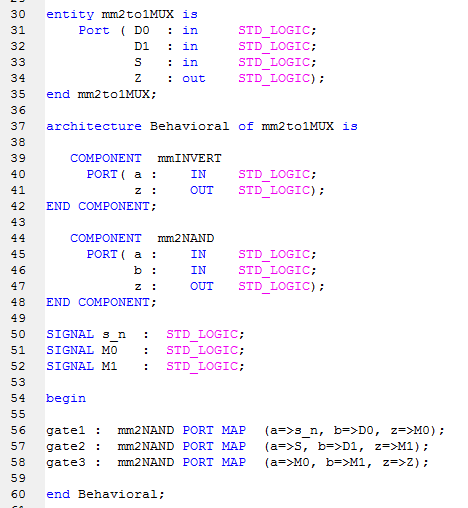

Ok I neex to make a 4 bit MUX using structural VHDL and I'm not sure if
I set it up correctly. I'm either mixing up how to correctly test the 4
bit MUX using a test bench waveform or I'm assigning the Select
incorrectly. I tested the 1 bit MUX and it worked fine.

Attached are images of my code
Attached files:
-

1bitMUX.PNG
9.4 KB -

4bitMUX.PNG
10 KB -

MUX_diagram.PNG
2.5 KB
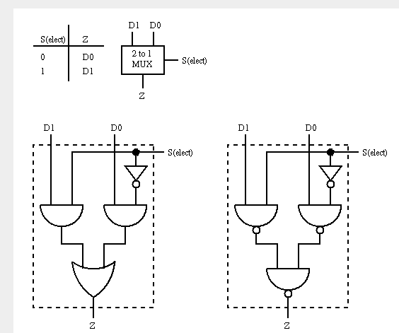
Do you want to get a 4-bit 2-to-1 mux (with 4 inputs, 1 select and 4
outputs), or do you want a single 4-to-1 mux (4 in, 2 select,1 out)?

BTW: do you program VHDL with pictures? No? So, why do you not simply
attach the *.vhd files?
Attached files:
-

1.PNG
5.2 KB
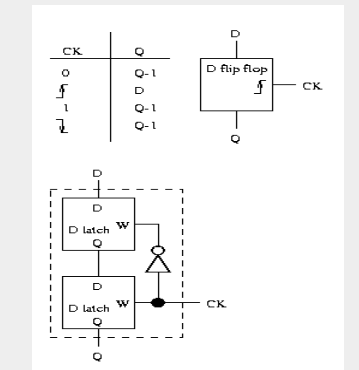
Sorry I have already solved that problem. I was using my pre-edited code
haha. However, I receive errors when I synthesize my flip flop. I get
errors stating:

WARNING:Xst:2170 - Unit MMFlipFlop : the following signal(s) form a
combinatorial loop: Q.

WARNING:Xst:2170 - Unit MMFlipFlop : the following signal(s) form a
combinatorial loop: M1.

Am I supposed to be receiving these combinatorial loop warnings? The
flip flop performed correctly when I did test bench tests. I figure
since I am doing structural VHDL, I should have 0 errors in order to
avoid problems down the road. Attached are the VHDL files and a picture
of my diagram.
mike mr wrote:
> Sorry I have already solved that problem.
And how?
(Just for information, if someone else needs help in fututre times...)


> However, I receive errors when I synthesize my flip flop. I get
> errors stating:
> WARNING:Xst:2170 - Unit MMFlipFlop : the following signal(s) form a
> combinatorial loop: M1.
These are no ERRORS but just simple WARNINGS. Thats a major difference!

> Am I supposed to be receiving these combinatorial loop warnings?
This messages come from your latches. A latch consists mainly of a
combinatorial loop from the Output to the input. But usually such loops
are made unintenionally, and so the synthesizer warns...

> The flip flop performed correctly when I did test bench tests. I figure
> since I am doing structural VHDL, I should have 0 errors in order to
> avoid problems down the road.
You get this error because you are doing structural VDHL. Everyone
else on the world would write something like this to get a D-FF:
1 | process (ck) begin |
2 | if rising_edge(ck) then |
3 | q <= d; |
4 | end if; |
5 | end process; |
With this the synthesizer immediatelly knows which component to use...

With your structural description the synthesizer tries to build a D-FF
out of a bunch of LUTs, not being able to recognize that there are
thousands of components laying around doing exactly what you want deep
inside.

As I already said: tell your teacher its a fairly stupid job waisting
time with a VHDL description style from the last millenium. The tools do
not expect such an old-fashioned coding style and they will produce
inefficient results. Why learning such things?
> And how?
> (Just for information, if someone else needs help in future times...)

Well it turns out that I didn't add the a gate for the inverter in the 2
to 1 MUX. Also in my 4 bit 2 to 1 MUX I should have had:


gate1  :  mm2to1MUX  PORT MAP(D0=>'0',D1=>D1(3),S=>S,Z=>Z(3));
gate2  :  mm2to1MUX  PORT MAP(D0=>'0',D1=>D1(2),S=>S,Z=>Z(2));
gate3  :  mm2to1MUX  PORT MAP(D0=>'0',D1=>D1(1),S=>S,Z=>Z(1));
gate4  :  mm2to1MUX  PORT MAP(D0=>'0',D1=>D1(0),S=>S,Z=>Z(0));


> This messages come from your latches. A latch consists mainly of a
> combinatorial loop from the Output to the input. But usually such loops
> are made unintenionally, and so the synthesizer warns...

I figured as much thanks for the info! This warning doesn't give me any
irregular ouputs so this shouldn't cause any errors in other components
when I use this 4 bit 2 to 1 MUX?

> As I already said: tell your teacher its a fairly stupid job waisting
> time with a VHDL description style from the last millenium. The tools do
> not expect such an old-fashioned coding style and they will produce
> inefficient results. Why learning such things?

I couldn't agree with you more! However, he will not use behavioral VHDL
as he believes the class will get a better understanding by doing
components individually and understanding how everything connects to
each other.

I'm trying to connect the 6 bit MUX(Ijust incremented it from 4 to 6) D0
signal to ground(0). However when I try and do so I get a bunch of
warnings:
1 | WARNING:Xst:647 - Input <D0> is never used. |
2 | Unit <mm6bitMUX> synthesized. |
3 | WARNING:Xst:1290 - Hierarchical block <gate1> is unconnected in block <gate1>. |
4 | It will be removed from the design. |
5 | WARNING:Xst:1290 - Hierarchical block <gate2> is unconnected in block <gate1>. |
6 | It will be removed from the design. |
7 | WARNING:Xst:1290 - Hierarchical block <gate1> is unconnected in block <gate2>. |
8 | It will be removed from the design. |
9 | WARNING:Xst:1290 - Hierarchical block <gate2> is unconnected in block <gate2>. |
10 | It will be removed from the design. |
11 | WARNING:Xst:1290 - Hierarchical block <gate1> is unconnected in block <gate3>. |
12 | It will be removed from the design. |
13 | WARNING:Xst:1290 - Hierarchical block <gate2> is unconnected in block <gate3>. |
14 | It will be removed from the design. |
15 | WARNING:Xst:1290 - Hierarchical block <gate1> is unconnected in block <gate4>. |
16 | It will be removed from the design. |
17 | WARNING:Xst:1290 - Hierarchical block <gate2> is unconnected in block <gate4>. |
18 | It will be removed from the design. |
19 | WARNING:Xst:1290 - Hierarchical block <gate1> is unconnected in block <gate5>. |
20 | It will be removed from the design. |
21 | WARNING:Xst:1290 - Hierarchical block <gate2> is unconnected in block <gate5>. |
22 | It will be removed from the design. |
23 | WARNING:Xst:1290 - Hierarchical block <gate1> is unconnected in block <gate6>. |
24 | It will be removed from the design. |
25 | WARNING:Xst:1290 - Hierarchical block <gate2> is unconnected in block <gate6>. |
26 | It will be removed from the design. |
What would the correct way to connect an input to ground? Attached is
the overall program counter diagram that I need to make. As you can see
D0 would be connected to '0' and D1 would be the output signal coming
from the adder.
mike mr wrote:
> gate1  :  mm2to1MUX  PORT MAP(D0=>'0',D1=>D1(3),S=>S,Z=>Z(3));
>
> I'm trying to connect the 6 bit MUX(Ijust incremented it from 4 to 6) D0
> signal to ground(0). However when I try and do so I get a bunch of
> warnings:
>  ......
> What would the correct way to connect an input to ground?
You are doing it the correct way, and the toolchain correctly recognizes
that it is not necessary to implement a static-'0' path in the mux. So
this path is optimised away.

To sum it up: thats the information I give my trainees, and thats the
information your teacher should give you. To bad that he doesn't...
Please log in before posting. Registration is free and takes only a minute.
Existing account
Do you have a Google/GoogleMail account? No registration required!
Log in with Google account
Log in with Google account
No account? Register here.