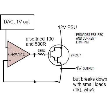
Hi!

I am trying to build a simple low noise PSU (Vref/DAC-OpAmp-NPN) and
everything works nicely, the emitter voltage follows the Vref/DAC
voltage, until I load the emitter (only 1k), which is when the emitter
voltage breaks down massively.

It is (or rather was? ;)) my understanding that the OpAmp will output
whatever voltage is necessary (up to ~3,5V in this case as I am using a
5V single supply "Rail-to-Rail" (yeah right as if -1,5V were "rail"...)
OpAmp) to see that same voltage appear on it's inverting input.

I am basically adhering to the LT1028 DS -
http://cds.linear.com/docs/Datasheet/1028fa.pdf and using the listed
2N6387. The NPN DS has no pinout (just numbers), but I assumed BCE.
Difference is only that input (C) is from a 12V lab PSU and I am using
unity gain with a different, unity-gain stable OpAmp (OPA140). I tried
varying the B resistor (I assume it needs ~3mA from DS and because the
DS uses 10V+330Ohm) from 100-500 Ohm, but to no avail...

What am I missing? I'm sure it's simple...

Thanks!
hi Patrick,
you're so right, it's really simply.
Sure that the pins of the darlington are connected well?
Seems not so, the voltage at the emitter is as stable as the voltage at
the collector. Take a look to the voltage of the base, it should be 0,8
to 1,2 V higher than the needed output. What current is required?
Perhaps there's no need for a darlington type, i think, the OPA140 can
drive 20mA or more, so you can get an output current of min. 2 Amps.
Kindly regards, harry
>What am I missing? I'm sure it's simple...

Forgot the internal biasing resistors of Darlington??
Suggestion:

Perhaps a high current flows trough the input protection diodes of the
opamp. Between the + and - input of the opamp are two antiparallel
'virtual' diode that start to conduct at difference voltages > 1.4 Volt.

Use a series resistor e.g. 2k2 at each of the + and - inputs to limit
the current.

Perhaps the circuit might be instable (oscillating) in some conditins,
but that should not be destructive for the darlington.

regards,
William
Hi!

If you are not sure about connecting the darlington transistor (B, C and
E): Most Multimeters have a transistor tester. Maybe u can use it to
determine correct pinning.

Yours,
Stefan
Please log in before posting. Registration is free and takes only a minute.
Existing account
Do you have a Google/GoogleMail account? No registration required!
Log in with Google account
Log in with Google account
No account? Register here.