hello,

I am writing a code in vhdl.
my main code consist of components and fsm
I am tring to move a component output port that been drive inside the
component to a output port signal that is inside the main entity.

the problem is that when I write inside the port map of the component in
the main entity and connect between the two directly I get a multi
driver error in modelsim
and in real life it got stuck.

could some one show my how can I assign the output component to my
output port in my entity?
> I get a multi driver error in modelsim
On which signal?


BTW:
use these two old Synopsys libs
  use ieee.std_logic_1164.all;
  use ieee.std_logic_arith.all;
OR (much better) this one
  use ieee.std_logic_unsigned.all;
But never both of them. Because otherwise some definitons are redundant
and you can get strange behaviour and curious errors...
I think your worng because i can't remove any of those library if I do I
get a lot of errors
thanks btw
I cannot see a multi source on this signals. Pls post the original
message and maybe a screenshot from the waveform display.
You should not assign a value to an output port of your component.
Change this in your TB:
signal  M_P_Pwm   :  std_logic;

> and in real life it got stuck.
This is definitly another problem!
the real problem is that I am trying to drive a robot with it and almost
every thing until I put every code in its on component.
yes but fixing the testbench won't fix that problem how could I solve
this?
btw M_P_PWM is not an output of a component it's an output of the main
entity
> yes but fixing the testbench won't fix that problem
Probably not.
> how could I solve this?
Yout testbench sould be a "picture" of the hardware connected to the
FPGA. And then if the testbench itself is ok, and the simulation
performs ok, you have a good chance that your design also works on real
hardware.
not very promissing for my
any way your solution doesn't work and when I changed the std_logic to
std_ulogic I get the error of the multi driver, and that won't change if
will fix the testbench I think I need to change the way I have connected
between the component output to the entity output
maybe with a signal or another port but I don't know how to that
I just figured out: you are instatiating both modules in your TB, and
connect the signal M_P_Pwm to two output ports...  :-o

Because the Motion_pwm is already a component of the fsm module, you
only must instatiate the fsm in your TB.
hu?? I think I understand it does solved it (if you could explain it to
my in more details I will appreciate it)
but still in real my fpga is gritting stuck at state execute just after
rising the enable and just before he should give the pwm control '1'
Correct way:
Motion_pwm is a component of fsm.
fsm is a component of fsm_tb.

Your way:
Motion_pwm is a component of fsm.
Motion_pwm and fsm are components of fsm_tb.

You see whats wrong?


In your TB this happens:
1 | test : entity work.fsm |
2 | port map ( ... M_P_Pwm=> M_P_Pwm ); |
3 | |
4 | motion_pwm_comp:Motion_Pwm |
5 | port map ( ... Pwm => M_P_Pwm ); |
The output of two components are driving the same signal.
thanks for the insight...
what about the main code the "fsm" is it correct to assign PWM <=
M_P_PWM?

btw this is only a very small partof the code because I have removed
every thing in order to find the problem ...

do you think you could find what's wrong with the code if I will send
you the orginal code? or at least tell my if there is a major mistake
that the compiler didn't tell my about ?
> but still in real my fpga is gritting stuck at state execute just after
> rising the enable and just before he should give the pwm control '1'
Is your simulation ok?
Maybe I forgot to mention: FIRST you have to fix the simulation. If the
simulation is ok and your module is doing what you expect, then you can
go on with real hardware...
yes my simulation is ok thank you ,and every thing is working as it
supposed to.
I don't remember if I mentioned it but before I have unit the fsm with
components every thing was in one long code and work more or less.

and now after my simulation of the unit components is working I still
need to remember that the test bench wasn't the cause for the robot
behavior only a guide to tell my I were is the problem which I knew
because I put a seven seg display for the states
so I guess you think I need to go bake to real hardware now?
I didn't fix nothing in the code only in the testbench
another thing I wanted to ask is about the libraries
with which library I should work with if not the std_logic , numric?
who can I change my project in order to work with the correct library or
only with as you said
"
use these two old Synopsys libs
  use ieee.std_logic_1164.all;
  use ieee.std_logic_arith.all;
OR (much better) this one
  use ieee.std_logic_unsigned.all;
But never both of them. Because otherwise some definitons are redundant
and you can get strange behaviour and curious errors..."
Ok that was a copy fail... :-/

What I meant is this:
DONT'T use the old Synopsys libs
  use ieee.std_logic_arith.all;
  use ieee.std_logic_unsigned.all;
  use ieee.std_logic_signed.all;
BUT use this one
  use ieee.std_logic_unsigned.all;
sorry to say but quartus isn't approving the use of std_logic without
those libraries
> sorry to say but quartus isn't approving the use of std_logic
Of course it is.
1 | library IEEE; |
2 | use IEEE.STD_LOGIC_1164.ALL; |
3 | use IEEE.NUMERIC_STD.ALL; |
This is the heading on all my VHDL files, see there:
http://www.lothar-miller.de
And in almost 90% thats enough.
Never there is one word of STD_LOGIC_ARITH.

> sorry to say but quartus isn't approving the use of std_logic
Of course you cannot do calculations on std_logic_vectors. But instead
you have the datatypes signed and unsigend and conversions/casts
from/to integer and std_logic_vector.
And that is in no case affected by quartus.
thats a nice site

so it's more complax to use numric std then std_logic
If your already here
Why when I create a modelsim project and after adding files i get a
compiler error  about "-nocoverfec" and I need to go and change the
settings that the error won't appear again?
> so it's more complax to use numric std then std_logic
No. IHMO its more straight forward and well defined. Each signal has its
type. With the Synopsys libs you will be trapped now or then.
Given this:
1 | library IEEE; |
2 | use IEEE.STD_LOGIC_1164.ALL; |
3 | use ieee.std_logic_arith.all; |
4 | use ieee.std_logic_unsigned.all; |
5 | :
|
6 | signal s : std_logic_vector (7 downto 0) := x"78"; |
7 | :
|
8 | output <= '0' when s < x"AF" else '1'; -- let this represent a very tricky part of code |
9 | :
|
And lets say you share "the tricky code" with your colleague because he
needs it. And your colleague is used to write:
1 | library IEEE; |
2 | use IEEE.STD_LOGIC_1164.ALL; |
3 | use ieee.std_logic_arith.all; |
4 | use ieee.std_logic_signed.all; -- only slightly different... :-o |
5 | :
|
6 | -- and from here: copy and paste...
|
7 | :
|
8 | signal s : std_logic_vector (7 downto 0) := x"78"; |
9 | :
|
10 | output <= '0' when s < x"AF" else '1'; -- let this represent your very tricky part of code |
11 | :
|
Do you expect the code to work as you wanted?
no its not the same ... unsigned and signed are differnt types there for
we will get differnt resulte
Attached files:
-

final.jpg
300 KB
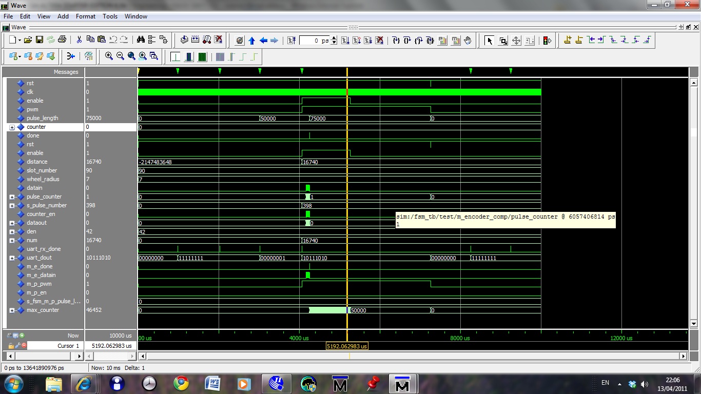
I want to show you the full simulation (well for one action)
We are working at the same hours (;
Do you have more materials on the numeric library ... its sounds
interesting and from the book I had learned from in the past weeks the
is no recollection of numeric as I remember at least

one more thing about the simulation do you think that its good that the
PWM signal is left high after I am finish with him.
I think that because the simulation isn't running in real timing the pwm
is left on high ... what do you think?
rotem rotemkim wrote:
> I want to show you the full simulation (well for one action)
> We are working at the same hours (;
> Do you have more materials on the numeric library ... its sounds
> interesting and from the book I had learned from in the past weeks the
> is no recollection of numeric as I remember at least
Look for a book from Peter Ashenden...

> one more thing about the simulation do you think that its good that the
> PWM signal is left high after I am finish with him.
It depends on your hardware. Usually that means "full on" to the power
stages.

> I think that because the simulation isn't running in real timing the pwm
> is left on high ... what do you think?
Simulation is of course not running in real time, but it is
simulating real time. Real simulation time is that reported on the
boottom lines. "NOW" is the simulation time. The cursor shows the time
at the cursors postition.
I have notice that the pwm counter doesn't run ... and I played with it
a little.
I think that the constant are not getting the values the need to get
inside the component why is that?
Hi again
I am sorry I didn't update the forum I have found the problem a while
ago
Some definition wasn't correct (copy paste mistake I wrote 20ms instead
of 20ns) and that made the design go crazy.
Any way I need to take out from my design the fsm stg from the state
machine viewer but I get a strange massage "unable to display state
transition due to long processing time" does someone know who to solve
this problem?.
In altera forum I was told to install the quartus 10 version and they
even showed me the transition state machine they got but it didn't work
for me.
Please log in before posting. Registration is free and takes only a minute.
Existing account
Do you have a Google/GoogleMail account? No registration required!
Log in with Google account
Log in with Google account
No account? Register here.