Ok, here we go:
I am building a SoundCard DAC for controlling my Laser.
The SC outputs from 0.7 to 3.1V whereby 2.55V is the "middle".
An Amplifier should convert this to a differential signal with 10V p-p.
currently not soldered anything to the SoundCard; im using a USB plug
for power and for testing the opamp's stage behavior, im was using a
1MOhm potentiometer to adjust any signal voltage between +5 and -5V.
now, after i thought the high resistance of it could be the error cause,
i replaced it with 3x 10k R's at which i can get 4 different voltages
for testing.
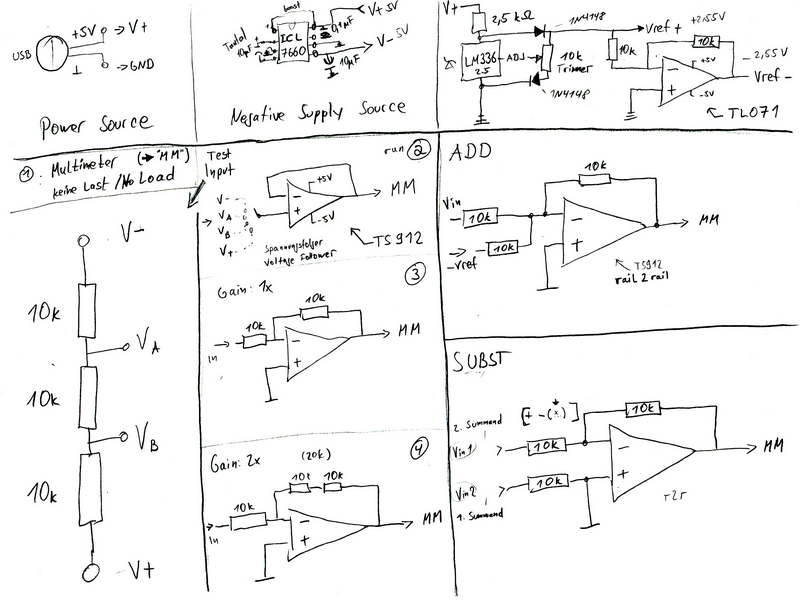
I attached my circuit plan, its exactly how i builded it. between
+5V/GND and -5V/GND are a 100µF elko each for stabilising, otherwise
currently no capacitors are used, except the ones for the ICL7660
negative voltage converter.
So i did a row of different measurements on different setups. Results
are attached to this Post, too.
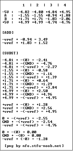
1 | 1 | 2 | 3 | 4
|
2 |
|
3 | -5V : -4.82 -4.80 +4.84 +4.95
|
4 | A : -1.55 -1.55 +0.94 +1.88
|
5 | B : +1.71 +1.71 -1.03 -2.06
|
6 | +5V : +4.99 +4.99 -4.74 -4.76
|
7 |
|
8 |
|
9 | [ADD]
|
10 |
|
11 | -vref + -0.94 = 3.49
|
12 | -vref + +1.03 = 1.52
|
13 |
|
14 |
|
15 | [SUBST]
|
16 |
|
17 | -4.81 + -(0) = -2.41
|
18 | -4.81 + -(GND) = -4.76
|
19 | -4.81 + -(-vref) = -2.27
|
20 | -1.55 + -(0) = -0.58
|
21 | -1.55 + -(GND) = -1.16
|
22 | -1.55 + -(-vref) = +1.39
|
23 | +1.71 + -(0) = +0.64
|
24 | +1.71 + -(GND) = +1.29
|
25 | +1.71 + -(-vref) = +3.84
|
26 | +4.99 + -(0) = +2.50
|
27 | +4.99 + -(GND) = +4.96
|
28 | +4.99 + -(-vref) = +4.95
|
29 |
|
30 | +vref + -(0) = +1.28
|
31 | +vref + -(GND) = +2.56
|
32 | +vref + -(-vref) = +4.95
|
33 |
|
34 | 0 + -(+vref) = -2.55
|
35 | GND + -(+vref) = -2.54
|
36 | -vref + -(+vref) = -4.76
|
37 |
|
38 | 0 + -(0) = 0.00
|
39 | GND + -(0) = 0.00
|
40 | -vref + (-0) = -1.28
|
In the table, the 1st collumn is just measured with multimeter on the
Vin 3*10k divider, withoud any load. second one is the divider voltages
feed into a voltage-follower opamp circuit, 3rd one is fed into
inverting-amplifier with 1x gain and 4rd finaly with 2x gain.

So this is strange. the "real" voltages on the divider are coming out
unaltered with a impendance amplifier / follower; but are changing
extreme when i use something with gain.
Also in the last test setup, the substractor, when i feed in 2.55V i got
the half out, without any other voltage is going in which could alter it
(0 in the table means unconnected cable)
On the other side, whenever i do operations with buffer stabilised
negative n/o directly from LM336 reference circuit Vref ±2.55V Voltage;
the output never differs from ideal theory values!


What the...?!


I never get "zero-level" signal output on 2.55V "offset-level" input. SC
is a CM106 so the Vref is set right. OPA's are rail2rail and able to
deliver Vout = Vsupply - 0.01V !
Here's a bigger scan:
http://www.abload.de/image.php?img=image0022ff8c.jpg